Worcester controls – Flowserve I90 Series User Manual
Page 16
16
Pulsair Loop-Powered Positioner Modular Accessory System (Series I90/L90)
WCAIM2053
C. PIEZO VALVE BLOCK
The Worcester/McCANNA Pulsair Series I90/L90 Loop-Powered
Positioner uses specially designed piezo-electric valves to control
a single-acting (spring-return) pneumatic actuator. One of the
valves is used to control the flow of air into the actuator; the other
to control the exhaust. This allows the actuator to “lock” in place.
The valve unit actually houses two high-flow, three-way spool
valves which are piloted by the piezo-electric elements. A piezo-
electric device is one that changes its shape when exposed to an
electrical potential (voltage). Only minute amounts of current are
required for this action to occur.
Air Supply Requirements and Technical Data
Air Supply:
Medium:
Industrial Air (or other non-corrosive gas),
must be dry and oil free
Pressure:
30–100 psi
Filtration:
< 30 micron required / 20 micron strongly
recommended
Dew Point:
< -40°F
Air Consumption:
(Settled State)
< .00824 SCFM
Unrestricted Air
Flow Through Valve
Inlet:
3.24 SCFM
(With 15 psi differential pressure)
Outlet:
2.94 SCFM
(With 15 psi differential pressure)
Type of Actuator:
Single-acting (spring-return) rotary
Mounting Position: Any, exhaust port not upwards
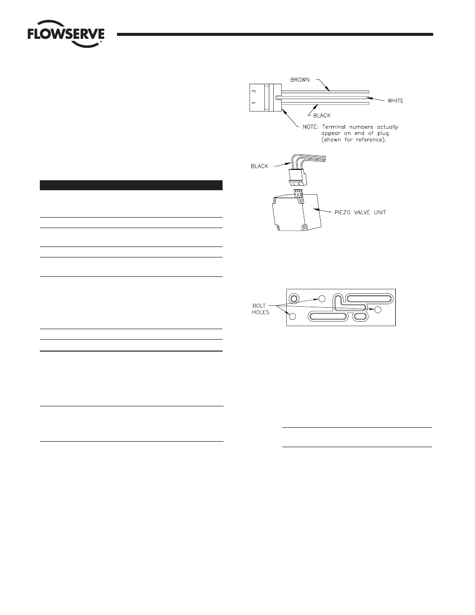
All lead wires are equipped with quick-connect plugs that are
easily connected/disconnected to the piezo valve unit. See Figure
14. Do not force the plugs together; damage can result. Do not
pull directly on wires when disconnecting the plugs — the wires
can be damaged and/or disconnected if abused.
CAUTION: The plug that connects to the piezo valve unit can be
assembled two ways. Be certain that the numbers on the plug
match the numbers on the valve unit as shown. The black wire
goes to terminal number 1.
The manifold block gasket has been designed to adapt the
manifold block to the Series 90 M.A.S. housing air connections.
The gasket is illustrated in Figure 15 for future reference in
these instructions.
1. ASSEMBLY (Refer to Figure 16)
a. SINGLE-ACTING LOOP-POWERED POSITIONING TYPE
NOTE: Where lubrication is required, Vaseline or other
non-corrosive grease is acceptable unless otherwise
noted. Use sparingly.
1. Attach the exhaust gasket (item 1) to the manifold
block (item 2) using two #4 x
>|zn" round head screws
(item 3).
CAUTION: Do NOT over-tighten screws, as this will
make it difficult to install piezo unit.
2. Insert the three #10-32 x
C|v" socket head screws
(item 4) through the manifold block from the side
shown (marked SR-L). Position the manifold block
gasket (item 5) on these screws.
3. Attach the manifold block and gasket to the angled
inside wall of the M.A.S. base using the three
#10-32 x
C|v" screws.
4. Install the piezo valve unit (item 6). Be certain that the
spring plunger (item 7) engages its location in the
piezo valve unit as well as the counterbore in the
manifold block. It will be necessary to apply light force
to compress the rubber portion of the exhaust gasket
and slip the piezo unit into place. There are two locator
Flow Control Division
Worcester Controls
Figure 15 – Single-acting (Spring-return)
Figure 14