Worcester controls – Flowserve I90 Series User Manual
Page 15
WCAIM2053
Pulsair Loop-Powered Positioner Modular Accessory System (Series I90/L90)
15
h. Plug (1)
Z|v" NPT and (1) Z\," NPT air connection ports
(labeled “D” and “A”) with the stainless steel pipe plugs
provided. Thread sealant is not recommended prior to
installing these plugs. The residue left by a thread sealing
compound could foul the piezo valve air passages.
Refer to the figures in Section III.C.1 for further
information.
i.
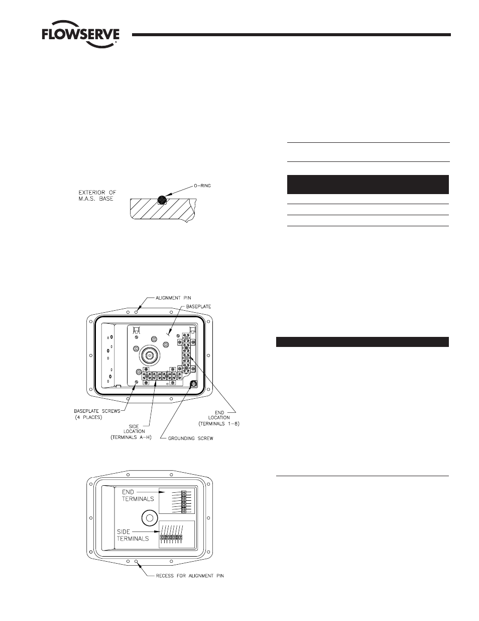
The M.A.S. uses a standard O-ring to achieve both
Watertight (TYPE 4) and Explosion-proof (TYPE 7)
ratings. Refer to Figure 11.
j.
Refer to Figure 12. The baseplate contains one or two
factory-assembled terminal strips, depending on selected
options. The “end” location is always used. A second
terminal strip is added to the “side” locations when
required as outlined below.
k. Assemble the baseplate into the base using the four #6-
32 screws provided. Use care when tightening these
screws as the baseplate is plastic and could be damaged
if over-tightened.
If options such as Switches, etc., are to be installed,
assemble them to the baseplate prior to installing
baseplate into base.
CAUTION: Avoid contacting baseplate with solvents –
damage may result.
Options Requiring
Second Terminal Strip
SPDT Switches
M2
Dual Potentiometer
P, 5
4-20 Output
4
l.
The base is provided with an alignment pin pressed into
the flange which will allow the cover to be assembled in
only one orientation (See Figures 12 and 13). Be certain
the cover is correctly positioned prior to tightening bolts
or damage may result.
m. M.A.S. options are supplied with wiring diagrams which
should be affixed to the inside of the cover as shown in
Figure 13. Note the orientation of the terminal strips on
the wiring diagrams, and their locations in the cover.
3. TROUBLESHOOTING
Problem
Possible Cause(s)
Solution
Shaft binds
Cover not centered
Loosen cover screws
and allow cover to
center on shaft.
Retighten cover
screws.
Inadequate lubrication Remove cover and
lubricate shaft hole
with bearing grease,
such as Cindol 2321.
If excessive wear or
galling is present,
shaft and affected
part of housing will
have to be replaced.
Flow Control Division
Worcester Controls
Figure 11
Figure 12
Figure 13