Wiring – Flowserve URB 1 User Manual
Page 11
11
■
Wire equipment in series. Star-type wiring is not permitted.
■
Interlink screens of control cables such that electrical continuity is
ensured and connect them once to the central earthing point (CEP).
■
If more than one system component is connected to a CAN bus
network provide the first and last equipment with a terminating resistor
of 120
Ω
, Fig. 2
■
The CAN bus line must not be interrupted while operating with one or
more system components.
Any interruption will open the control circuit!
If the switching controller has to be replaced be sure to remove first
the terminal strips , Fig. 4
Note: Make sure that all system components connected are
not
operating before removing the CAN bus line from the terminal strip!
Wiring
Wiring diagram
For wiring diagram refer to page 4.
Attention
Note that multi-core control cable with conductors linked in pairs, e. g. UNITRONIC
®
BUS CAN 2 x 2 x .. mm
2
or RE-2YCYV-fl 2 x 2 x .. mm
2
.
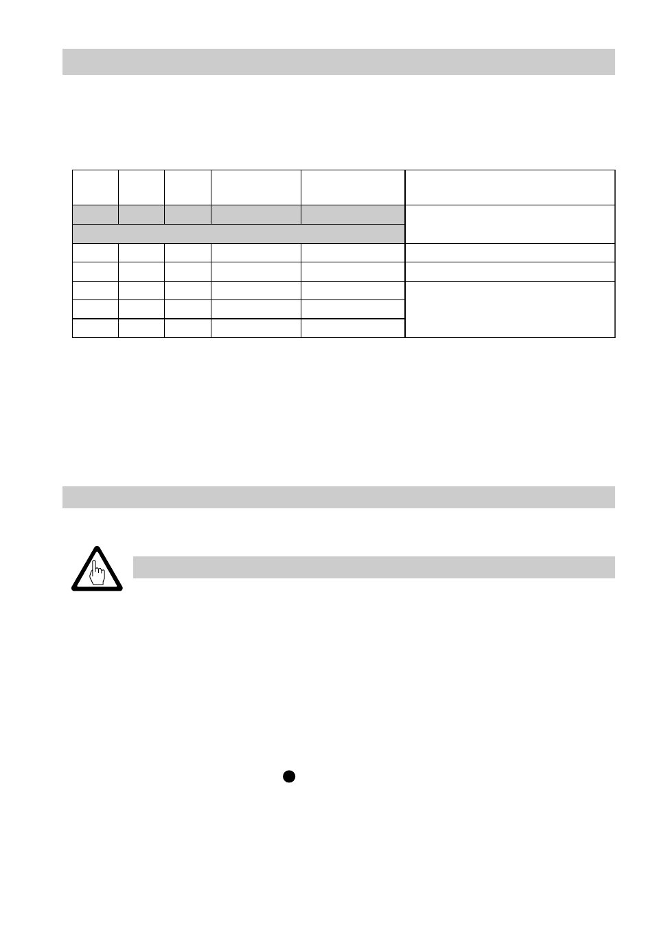
The baud rate (data transfer rate) dictates the cable length between the bus nodes
and the total power consumption of the sensors dictates the conductor size.
8
S
9
S
0
1
S
e
t
a
r
d
u
a
B
h
t
g
n
e
l
e
l
b
a
C
s
r
i
a
p
f
o
r
e
b
m
u
N
m
m
[
e
z
i
s
r
o
t
c
u
d
n
o
c
d
n
a
2
]
F
F
O
N
O
F
F
O
s
/
t
i
B
k
0
5
2
m
5
2
1
4
3
,
0
x
2
x
2
s
g
n
i
t
t
e
s
y
r
o
t
c
a
F
N
O
N
O
F
F
O
s
/
t
i
B
k
5
2
1
m
0
5
2
5
,
0
x
2
x
2
F
F
O
F
F
O
N
O
s
/
t
i
B
k
0
0
1
m
5
3
3
5
7
,
0
x
2
x
2
N
O
F
F
O
N
O
s
/
t
i
B
k
0
5
m
0
0
5
n
o
t
n
e
d
n
e
p
e
d
,
t
s
e
u
q
e
r
n
o
n
o
i
t
a
r
u
g
i
f
n
o
c
s
u
b
F
F
O
N
O
N
O
s
/
t
i
B
k
0
2
m
0
0
0
1
N
O
N
O
N
O
s
/
t
i
B
k
0
1
m
0
0
0
1
The baud rate is set via a code switch. Reduce baud rate if cable is longer than
specified in the table above. Make sure that all bus nodes feature the same settings.
To protect the switching contacts fuse circuit with 2.5 A (anti-surge fuse) or according
to TRD regulations (1.0 A for 72 hrs operation).
When a max. cable length of more than 125 m (up to 1000 m) is desired, make
sure to modify the baud rate accordingly. Refer to pages 75 and 76 for more
details.
B
UNITRONIC
®
is a registered trademark of LAPP Kabelwerke GmbH, Stuttgart.