Basic settings – Flowserve URB 1 User Manual
Page 23
23
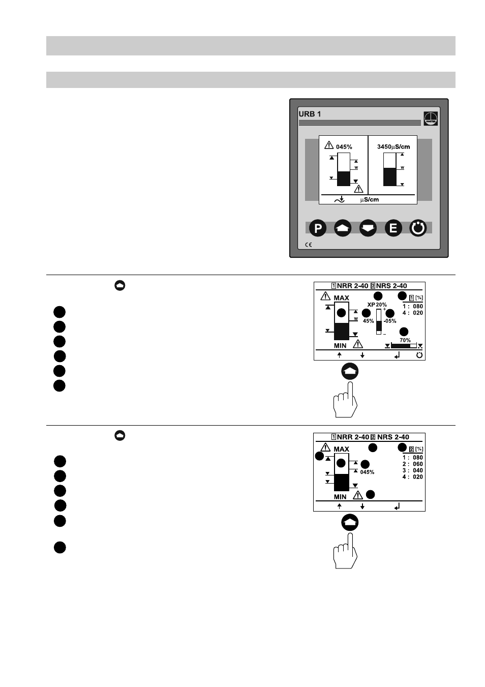
Press button briefly to enter the display
window of the level controller NRR 2-40.
Actual level (graphical representation)
Actual level (percentage)
Setpoint deviation
Proportional band X
p
Switchpoints NRR 2-40
Valve position
Press button briefly to enter the display
window of the level switch NRS 2-40.
Actual level (graphical representation)
Actual level (percentage)
Control unit 2 highlighted
Switchpoints for control unit 2
Low-level signal
(flashes in the event of an LW alarm)
High-level signal
(flashes in the event of an HW alarm)
LW = low water (limiter NRS 1-40)
HW = high water (limiter NRS 1-41
Basic Settings
– continued –
Visual display / Parameterisation of bus devices
The split-screen display window shows which
GESTRA bus devices can be indicated:
■
High-level limiter type NRS 1-41
■
Low-level limiter type NRS 1-40
■
Level switch type NRS 2-40
■
Level controller type NRR 2-40
■
Conductivity controller type LRR 1-40
1
2
3
4
5
6
1
2
3
4
5
6
2
3
4
5
6
1
2
3
4
5
6
1
briefly
briefly