Basic settings – Flowserve URB 1 User Manual
Page 42
42
Basic Settings
– continued –
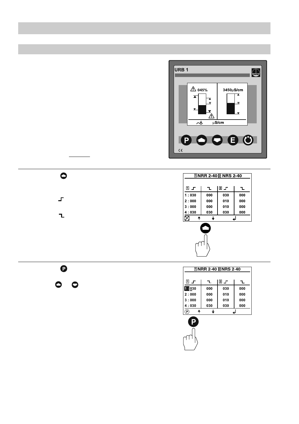
Setting relay delay times
Press button once briefly to activate
the line editing mode.
Use button or to scroll back and
forth through the lines.
The split-screen window shows which
GESTRA bus devices can be indicated:
■
High-level limiter NRS 1-41
■
Low-level limiter NRS 1-40
■
Level switch NRS 2-40
■
Level controller NRR 2-40
■
Conductivity controller LRR 1-40
Before commissioning the installation set
the relay delay times for the individual
switchpoints.
Note that the relay delay times of the
low-level and high-level limiters are
factory set and cannot be changed with
the URB 1.
Press button four times briefly to enter
the window for setting the relay delay times
of the switchpoints.
The symbol stands for relay energizing
delay.
The symbol stands for relay de-
energizing delay.
A number, for instance “001” corresponds
to a delay time of 100
msec. The value
“030” corresponds to 3 sec and the max.
value “255” corresponds to 25.5 sec.
4 times briefly
once briefly