Flowserve URB 1 User Manual
Page 9
9
Function
Explanatory Notes
– continued –
System description
– continued –
The URB 1 communicates with other GESTRA system components via a designated
CAN bus using the CANopen protocol to DIN ISO 11898.
The URB 1 can also be used to operate and display further system components
during operation.
■
Capacitance level switch type NRS 2-40 CANopen
■
Level controller type NRR 2-40 CANopen
■
Conductivity level switch type NRS 1-42 CANopen
■
Low-level alarm to TRD 604/EN type NRS 1-40 CANopen
■
High-level alarm to TRD 604/EN type NRS 1-41 CANopen
■
Conductivity controller and limiter to TRD 604/EN type NRS 1-41 CANopen
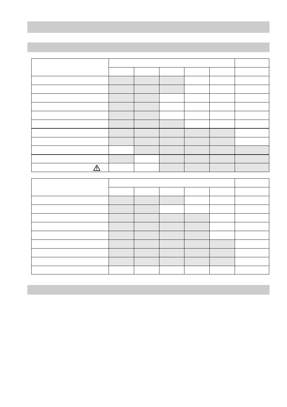
Standard display information
Level
Conductivity
NRS 1-40 NRS 1-41 NRS 1-42 NRS 2-40 NRR 2-40
LRR 1-40
Actual value (bar chart)
●
●
●
Actual value (numerical value)
●
●
●
Switchpoint (symbol)
●
●
●
●
High level alarm (electrode HW)
●
●
●
●
Low level alarm (electrode LW)
●
●
●
●
Manual/automatic operation
●
●
●
Stand-by mode
●
Unit [µS/cm] or [ppm]
●
Low level limit
●
High level limit
●
Alarm (warning triangle)
●
●
Further display information
Level
Conductivity
NRS 1-40 NRS 1-41 NRS 1-42 NRS 2-40 NRR 2-40
LRR 1-40
Actual value (continuous)
●
●
●
Switchpoints
●
●
●
●
Setpoint
●
●
Deviation
●
●
Valve position
●
●
Intermittent blowdown
●
Intermittent blowdown interval
●
Purging pulse 24 h
●
Current CAN bus addresses
●
●
●
●
●
●