Wiring – GAI-Tronics 352-7xx Division 1 VoIP Page Phones - Wired and WiFi User Manual
Page 11
Pub. 42004-486B
Model 352-7xx and 352-8xx Division 1 VoIP Page Phones – Wired & WiFi
Page 11 of 29
f:\standard ioms - current release\42004 instr. manuals\42004-486b.doc
12/14
Wiring
WARNING
The front cover is not hinged to the rear enclosure. When the cover bolts
are removed, the cover must be adequately supported.
1. While supporting the front cover, remove the ten cover bolts on the enclosure flange. Pull the front
cover far enough away to expose the internal connections. Flip the front cover 180º to the left, and
attach the front cover to the rear enclosure using the top left bolt hole. Rotate the cover
approximately 10º from vertical and place a second bolt in the bottom left rear enclosure hole. Allow
the cover to rotate against the bottom bolt. Hand-tighten both bolts to secure. Do not over tighten.
CAUTION
Do not scratch or nick the flanges of the front cover or rear enclosure.
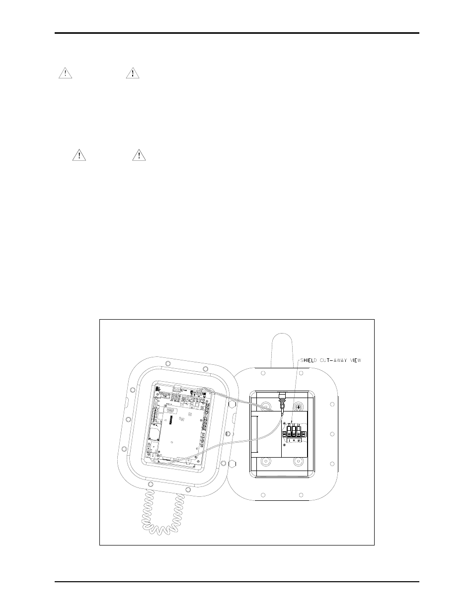
2. For wired versions, plug the incoming Cat5 data line to the network Cat5 cable receptacle on the
underside of the VoIP PCBA. See Figure 10. Remove the power supply cover in the rear enclosure
for access to the terminal block.
3. Remove the power supply cover in the rear enclosure for access to the input power terminal block.
Connect incoming power to the 3-point terminal in the rear enclosure.
4. Route the speaker connection wire on the left side of the power supply to the P4 speaker plug on the
front cover. Terminate the wires per the PCBA silk screen text.
5. Reattach the power supply cover using the two screws previously removed from the cover.
Install any additional connections as indicated below. Refer to Figure 10 for wiring details. Refer to
Table 4 on page 14 for the recommended conductor sizes.
Figure 9. Installation and Maintenance Configuration