Status indication, Power, Heartbeat – GAI-Tronics 352-7xx Division 1 VoIP Page Phones - Wired and WiFi User Manual
Page 14: Eact, Wifi activity (wifi units only), Wifi ready (wifi units only), Wifi connected (wifi units only)
Pub. 42004-486B
Model 352-7xx and 352-8xx Division 1 VoIP Page Phones – Wired & WiFi
Page 14 of 29
f:\standard ioms - current release\42004 instr. manuals\42004-486b.doc
12/14
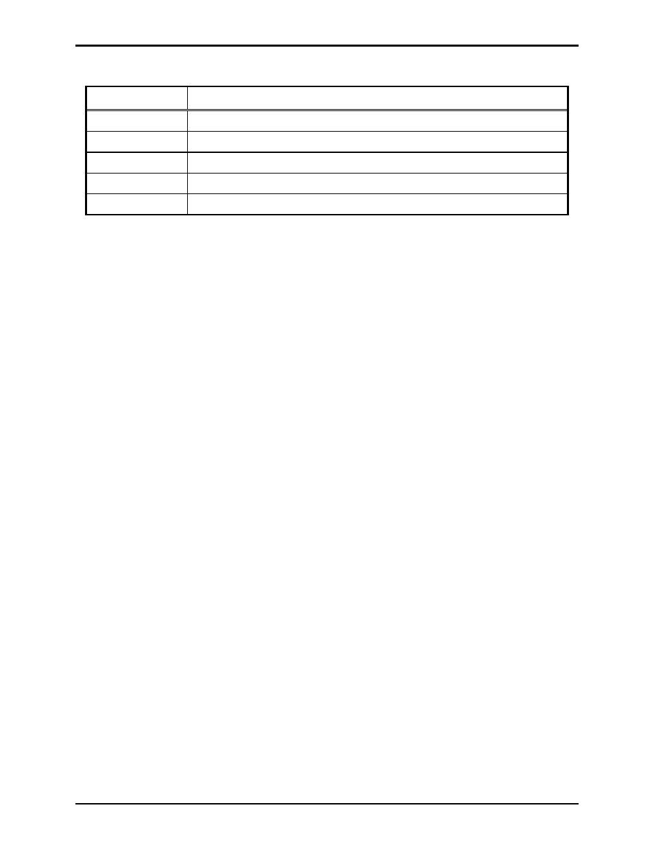
Table 4. Recommended Cabling
Cable Use
Size
LAN
Cat5 or Cat5e UTP cable with an RJ45 connector
Power
Two-conductor, No. 18 AWG is typical
Inputs
Two-conductor, No. 22 AWG is typical
Output contacts
Two-conductor, No. 18 AWG is typical
Speaker
Two or three-conductor, No. 18 AWG is typical
Status Indication
Power
The Power LED located on the VoIP PCBA illuminates when power is applied to the telephone. Refer to
Figure 11 for location.
Heartbeat
The Heartbeat LED located on the VoIP PCBA will flash when the telephone is operational over the
WLAN. Refer to Figure 11 for location.
EACT
The EACT LED located on the VoIP PCBA will turn ON when VoIP PCBA is connected to an Ethernet
device and flash when data is being transmitted. Refer to Figure 11 for location.
WiFi Activity (WiFi Units Only)
The WiFi Activity LED located on the WiFi module will turn ON when the VoIP Telephone is powered
and flash when data is being transmitted. Refer to Figure 11 for location.
WiFi Ready (WiFi Units Only)
The WiFi Ready LED a green LED on the RJ-45 connecter J2 located on the VoIP carrier PCBA
illuminates when the WiFi Interface is ready to connect to a wireless Network. Refer to Figure 11 for
location.
WiFi Connected (WiFi Units Only)
The WiFi Connected LED a yellow LED on the RJ-45 connecter J2 located on the VoIP carrier PCBA
illuminates when the WiFi Interface is connected to a wireless network or device. Refer to Figure 11 for
location.