Inputs, Outputs – GAI-Tronics 352-7xx Division 1 VoIP Page Phones - Wired and WiFi User Manual
Page 13
Pub. 42004-486B
Model 352-7xx and 352-8xx Division 1 VoIP Page Phones – Wired & WiFi
Page 13 of 29
f:\standard ioms - current release\42004 instr. manuals\42004-486b.doc
12/14
I/O
Inputs
Four auxiliary inputs have been provided for customer use. Terminations for these inputs are provided on
terminal block P12. Connect each input between the desired input (INPUT 1–4) and common (GND) on
terminal block P12. Refer to the “Inputs” section of Pub. 42004-396 for programming instructions for
these inputs.
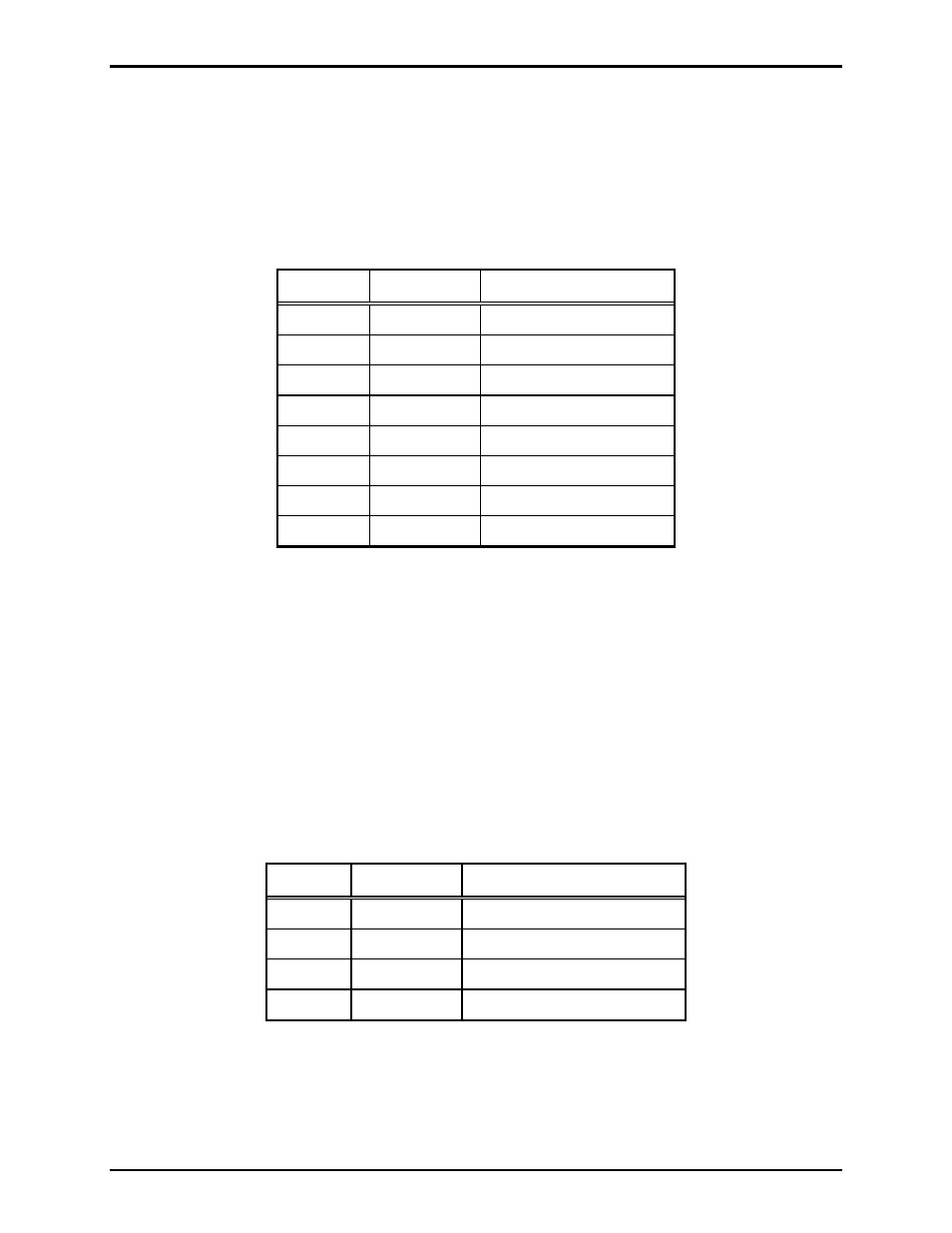
Table 2. Auxiliary Inputs – P12
Pin Label
Function
1 IN4
Input
4
2 COM Common
3 IN3
Input
3
4 COM Common
5 IN2
Input
2
6 COM Common
7 IN1
Input
1
8 COM Common
Inputs have an internal pull-up resistor and need to be 3.3 V dc tolerant.
Outputs
Two outputs have been provided for customer use. Terminations for these outputs are provided on
connector P10.
The function of each output is configurable. Outputs can be configured for one of the following modes:
On, Off, Pulse, Mute, Ring, Call, Connect, Hook, In Use, Ring Cadence, Ring Out, Page, Registered, or
Emergency. In some modes, the duration of the activation or on/off times can also be set. Refer to the
“Logic Settings” section of GAI-Tronics Pub. 42004-396, “VoIP Telephone Configuration Guide” for
more details.
Table 3. Output Contacts – P10
Pin Label
Description
1
C1
Common Output 1
2
NO1
Normally Open Output 1
3
C2
Common Output 2
4
NO2
Normally Open Output 2
Relay capacity is 5 amps, 30 V ac/V dc.