Attach the front cover – GAI-Tronics 352-7xx Division 1 VoIP Page Phones - Wired and WiFi User Manual
Page 15
Pub. 42004-486B
Model 352-7xx and 352-8xx Division 1 VoIP Page Phones – Wired & WiFi
Page 15 of 29
f:\standard ioms - current release\42004 instr. manuals\42004-486b.doc
12/14
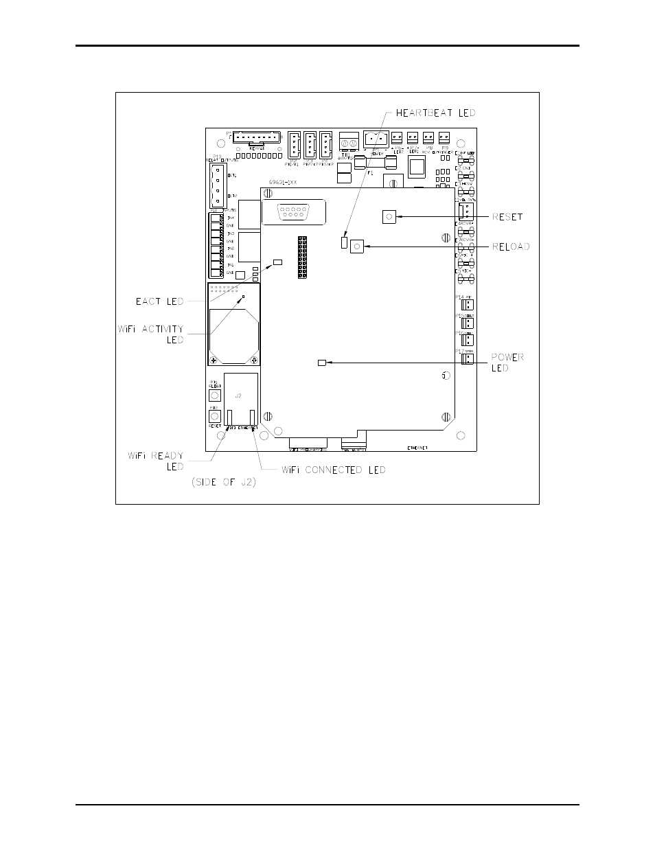
Figure 11. VoIP Carrier PCBA Component Locations
Attach the Front Cover
After all adjustments have been completed, inspect and clean the machined flange joint surfaces of both
the cover and box. Surfaces must be smooth, free of nicks, scratches dirt or any foreign particle build-up
that would prevent a proper seal. Surfaces must seat fully against each other to provide a proper
explosion-proof joint. Clean surfaces by wiping with a clean lint-free cloth.
Apply a light coat of Killark “LUBG” lubricant to flange surfaces and close the cover. Install and tighten
all cover bolts to 30 ft-lbs. Make certain no cover bolts are omitted. Use only those bolts supplied with
the enclosure.
N
OTE
: Refer to the Killark Installation, Operation, and Maintenance Data Sheet for the Killark Part. No.
EXB-684 N34 Base Enclosure (enclosed with the unit) for additional information.