Figure 10 – Gasboy 03908X User Manual
Page 13
MDE-4351A Gasboy ATC Kits 039086 and 039087 Installation Manual • February 2006
Page 13
Installation
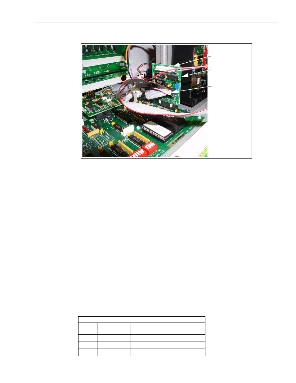
Figure 10: 460A4 Circuit Board in Place with Connections Made
19
In the kit, locate the W171 2-wire harness for IS Barrier.
20
Place the connector on the harness on P5 of the LP-70 Polycase box (
).
21
Using two of the crimp splices, connect the wires of the harness to the wires extending from
the top of the IS barrier. Match color codes.
22
Using an OM0205 cap or an appropriate size wire nut (OM0205 cap or wire nut is not part or
the kit), cap the end of the green wire from the IS barrier.
23
Connect the ground wire (wire with eyelet connector) to the nearest true ground.
24
Disconnect cable going to P6 connector of the Pump CPU board.
25
Connect the cable that was disconnected in previous step to P9 connector in the LP-70
Polycase box.
26
If the user wants to be able to display electronic totals, a second cable (C06003) must be
installed and connected to the P6 connector on the Pump CPU board.
27
In the LP-70 Polycase box, locate the DIP switches shown in
and set the switches for
the proper unit as shown in the following table:
DIP Switch Settings
Switch
Number
Switch Function
Settings
1
Product 1
ON for Diesel, OFF for Gasoline
2
Product 2
ON for Diesel, OFF for Gasoline
3
Not used
W283 Display Adapter
Connector on J4
J4
460A4 Circuit
Board Assembly