Figure 16, Figure 17 – Gasboy 03908X User Manual
Page 19
MDE-4351A Gasboy ATC Kits 039086 and 039087 Installation Manual • February 2006
Page 19
Installation
12
In the kit, locate the 460A4 Circuit Board Assembly (see
for identity). Connect the
assembly to the jack labeled LCD Display on the 9800 CPU PCB.
13
Reconnect the connector removed in Step 11 to the 460A4 Circuit Board Assembly jack J1 (in
center of board).
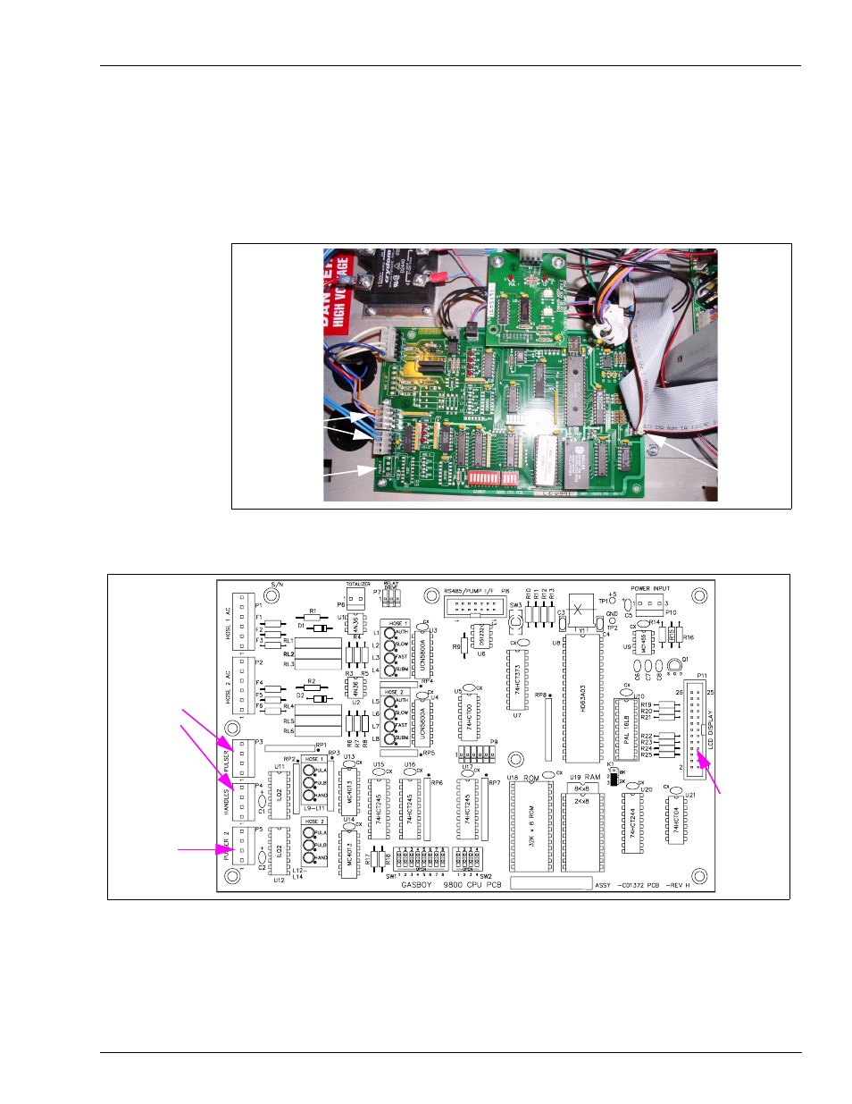
Figure 16: C06392 9800 CPU Printed Circuit Board (Photograph)
Figure 17: C06392 9800 CPU Printed Circuit Board (Drawing)
14
In the kit, locate the two W284 Pulser/Handle Ribbon Cables (see
for identity).
15
Connect one end of one W284 cable to P1 on the 461A2 board (
) and the other end to
P2 in the LP-70 Polycase box (
Pulser 1 and
Handles Jacks
Pulser 2 Jack
LCD
Display
Jack
Pulser 1 and
Handles Jacks
Pulser 2 Jack
LCD
Display
Jack