Db110 electric - adjustments – Kreg DB55 Pneumatic Foreman Pocket-Hole Machine User Manual
Page 12
R
DB110 Electric - Adjustments
11.
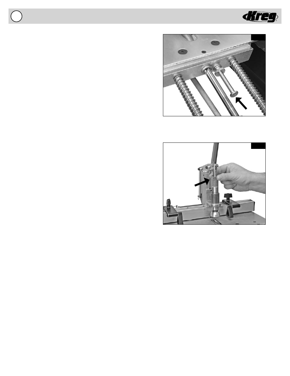
Fig. 7A
Fig. 7B
The Depth Stop Adjustment Screw limits travel
of the Drill Bit.
The Clamping Mechanism should be adjusted so that
it clears the workpiece by 1/8”.
Adjusting the Drill Bit Depth Stop
(Fig. 7A)
A Drill Bit Depth Stop is provided to stop the Drill Bit forward motion.
Before adjusting the Drill Bit Depth Stop make certain your machine
is DISCONNECTED from the ELECTRICAL SUPPLY. Without an
electrical supply you can be certain the machine will not accidentally
engage while you are performing this adjustment. The Depth Stop
Adjusting Screw should be adjusted so that the pilot point of the
Drill Bit is just slightly away from the Fence when the Motor Mount
contacts the head of the Depth Stop Adjusting Screw. Make sure the
Depth Stop Adjusting Screw is locked into position with the Depth
Stop Lock Nut.
1. Disconnect the machine from the electrical supply.
2. Remove the Black Acrylic Top to gain access to the inside of
the machine.
3. Loosen the Depth Stop Lock Nut on the Depth Stop Adjusting
Screw. Turn the Depth Stop Adjusting Screw to the approximate
position.
4. Pull the Handle until the Drill Bit pilot point is slightly away
from the Fence.
5. Adjust the Depth Stop Adjusting Screw till the Head contacts the
Motor Mount.
6. Tighten the Lock Nut to lock the Depth Stop Adjusting Screw in
position.
7. Place the Black Acrylic Top back on the machine.
Adjusting the Clamping Pad Height
(Fig. 7B)
The Clamping Pad can be adjusted for material of different
thicknesses. The factory setting will clamp materials of approximate
thicknesses of 3/4”. For materials thicker than 3/4”, the Clamping
Pad will need to be moved upward to allow the material to locate
below the Clamp Pad. For materials less than 3/4” in thickness
adjust the Clamping Pad downward to a gap of 1/8” above the
material. Before adjusting the Clamping Pad make certain your
machine is DISCONNECTED from the ELECTRICAL SUPPLY.
Without an electrical supply you can be certain the Drill Bit will not
accidentally rotate while you are performing this adjustment.
1. Rotate the Brass Lock Nut away from the Adjustment Shaft
and up the Hold Down Bolt to free the rotation of the
Adjustment
Shaft.
2. Rotate the Adjustment Shaft up the Hold Down Bolt to allow a
1/8” gap above the material under the Clamping Pad.
3. Tighten the Brass Lock Nut against the Adjustment Shaft
to prevent the accidental movement during normal drilling
operations.