Assembly instructions - db55 pneumatic – Kreg DB55 Pneumatic Foreman Pocket-Hole Machine User Manual
Page 9
R
Assembly Instructions - DB55 Pneumatic
8.
Handle with bolts, washers, and nuts
properly installed
Thread the anchoring bolt into the bottom of the
Clamping Tower.
Remove the Fill Cap and fi ll the Lubricator.
Fig. 4A
Fig. 4B
Fig. 4C
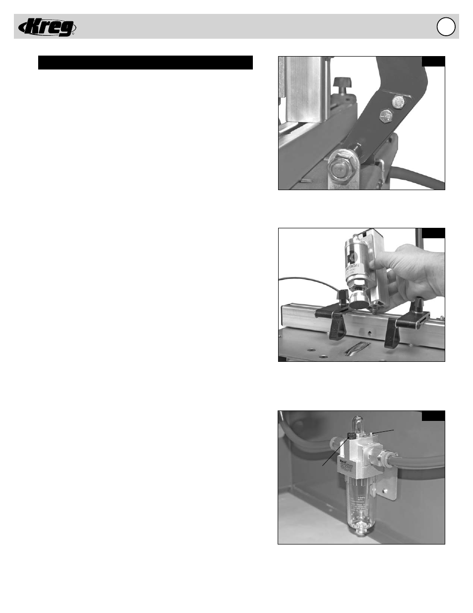
Fill Cap
Adjustment
Screw
Semi-Automatic Pneumatic Foreman DB55 Assembly
Assemble the Handle
(Fig. 4A)
The Handle for the Foreman is disconnected for shipping purposes.
The handle is shipped with two nut and bolt sets installed fi nger
tight in the Handle and Operator Assembly.
1. Remove both nuts and washers from their respective bolts and
align
the
fi rst set of holes in the Handle and the Operator
Assembly.
2. Push the fi rst bolt through the Handle and Operator Assembly
and attach the washer and nut.
3. Align the second set of holes in the Handle and the Operator
Assembly and push the second bolt through the Handle and
Operator Assembly and attach the remaining washer and nut.
4. Tighten both nut and bolt sets.
Attach the Pneumatic Clamping Tower
(Fig. 3B & 4B)
To attach the Pneumatic Clamping Tower a bolt must be secured
that is located on the underside of the machine. This operation
may be performed with the machine placed on its side on a
workbench to more easily reach the bolt. Refer to fi gure 3B and
4B for assembly. Location of the bolt is the same for electric and
pneumatic models.
1. Remove all packing material from the Pneumatic Clamping
Tower prior to attaching the Tower to the Fence. The Air
Cylinder is connected to the machine via the small diameter
air supply line, be careful not to twist or disconnect the air
supply line during assembly.
2. The anchoring bolt for the Clamping Tower passes through
the EZ DB Fence and is held in position with a nut for shipping
purposes. Remove the Nut from the 5/16-18 Bolt and use a ¼”
Allen Wrench to thread the anchoring bolt into the bottom of
the
Clamping
Tower.
You
may
fi nd it easier to temporarily
disconnect the connecting rod during this operation.
3. Align the Clamping Tower so it sits squarely on the EZ DB
Fence and tighten the anchoring bolt.
Fill the Automatic Oil Lubricator
(Fig. 4C)
The Automatic Oil Lubricator is void of Air Tool Oil for shipping
purposes. A 2-ounce bottle of air tool oil is provided with the
machine and should be used to fi ll the Lubricator. Operation of
the Automatic Oil Lubricator is discussed in the “ADJUSTMENTS” –
“Automatic Oil Lubricator” section of this manual.
1. Remove the Fill Cap of the Lubricator and add air tool oil
to
the
Lubricator.
2. Replace the Fill Cap in the Lubricator and tighten.