Assembly instructions - db110 electric – Kreg DB55 Pneumatic Foreman Pocket-Hole Machine User Manual
Page 8
R
Assembly Instructions - DB110 Electric
7.
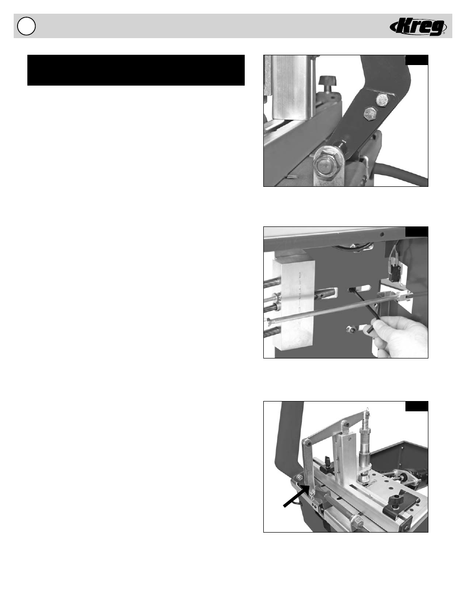
Fig. 3C
Align the Transfer Bars to the outside of the cam
contained on the operator assembly.
Fig. 3A
Fig. 3B
The anchoring bolt is accessed from under the machine
(You may fi nd it easier to temporarily disconnect the
connecting rod during this operation.)
Handle with bolts, washers, and nuts
properly installed.
Transfer
Bars
Semi-Automatic Electric Foreman DB110 Assembly
Entirely electric, no compressed air needed.
Motor rated at 3/4-HP and 8-amps
Assemble the Handle
(Fig. 3A)
The Handle for the Foreman is disconnected for shipping purposes.
The handle is shipped with two nut and bolt sets installed fi nger tight
in the Handle and Operator Assembly.
1. Remove both nuts and washers from their respective bolts
and align the fi rst set of holes in the Handle and the Operator
Assembly.
2. Push the fi rst bolt through the Handle and Operator Assembly
and attach the washer and nut.
3. Align the second set of holes in the Handle and the Operator
Assembly and push the second bolt through the Handle and
Operator Assembly and attach the remaining washer and nut.
4. Tighten both nut and bolt sets.
Attach the Mechanical Clamping Tower
(Fig. 3B & 4B)
To attach the Mechanical Clamping Tower a bolt must be secured
that is located on the underside of the machine. This operation may
be performed with the machine placed on its side on a workbench to
more easily reach the bolt. Refer to fi gure 3B and 4B for assembly.
Location of the bolt is the same for electric and pneumatic models.
1. Remove all packing material from the Mechanical Clamping
Tower prior to attaching the Tower to the Fence.
2. The anchoring bolt for the Clamping Tower passes through the
EZ DB Fence and is held in position with a nut for shipping
purposes. Remove the Nut from the 5/16-18 Bolt and use a ¼”
Allen Wrench to thread the anchoring bolt into the bottom of
the Clamping Tower. (You may fi nd it easier to temporarily
disconnect the connecting rod during this operation.)
3. Align the Clamping Tower so it sits squarely on the
EZ DB Fence and tighten the anchoring bolt.
Connect the Clamping Linkage
(Fig. 3C)
The Transfer Bars are disconnected from the Operator Assembly for
shipping purposes. You will need to attach each Transfer Bar to the
sides of the cam contained on the Operator Assembly.
1. Remove the 1/4” diameter X 3/4” long Clevis and Cotter Pin
from the Operator Assembly.
2. Align each of the Transfer Bars outside the cam on the
Operator
Assembly.
3. Push the Clevis through the aligned holes and attach the
Cotter
Pin.