Db55 pneumatic - adjustments – Kreg DB55 Pneumatic Foreman Pocket-Hole Machine User Manual
Page 16
R
DB55 Pneumatic - Adjustments
15.
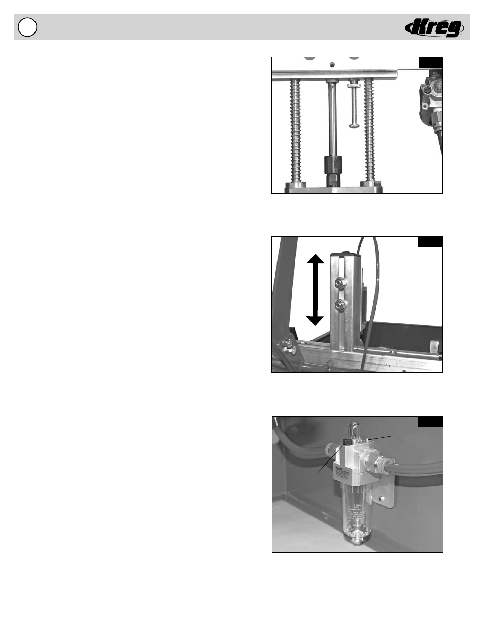
Fill Cap
Adjustment
Screw
Fig. 11A
The Depth Stop Adjustment Screw limits travel
of the Drill Bit.
Use the 1/2” Nuts to lock the Clamping Cylinder
in position
The Lubricator automatically adds the proper amount
of oil to the air system to prolong Air Motor life.
Fig. 11B
Fig. 11C
Adjusting the Drill Bit Depth Stop
(Fig. 11A)
A Drill Bit Depth Stop is provided to stop the Drill Bit forward motion.
Before adjusting the Drill Bit Depth Stop make certain your machine
is DISCONNECTED from the AIR SUPPLY. Cycle the machine via the
Handle to remove air from the system. Without an air supply you can
be certain the machine will not accidentally engage while you are
performing the adjustment. The Depth Stop Adjusting Screw should
be adjusted so that the pilot point of the Drill Bit is just slightly away
from the Fence when the Motor Mount contacts the head of the Depth
Stop Adjusting Screw. Make sure the Depth Stop Adjusting Screw is
locked into position with the Depth Stop Lock Nut.
1. Disconnect the machine from the air supply.
2. Remove the Black Acrylic Top to gain access to the inside of
the machine.
3. Loosen the Depth Stop Lock Nut on the Depth Stop Adjusting
Screw. Turn the Depth Stop Adjusting Screw to the approximate
position.
4. Pull the Handle till Drill Bit pilot point is slightly away from
the
Fence.
5. Adjust the Depth Stop Adjusting Screw till the Head contacts
the Drill Motor Mounting Block.
6. Tighten the Depth Stop Lock Nut to lock the Depth Stop
Adjusting Screw in position.
7. Place the Black Acrylic Top back on the machine.
Adjusting the Clamping Cylinder Height
(Fig. 11B)
The Clamping Cylinder can be adjusted for material of different
thicknesses. The factory setting will clamp materials of approximate
thicknesses between 1/2” and 3/4”. For materials thicker than 7/8”,
the Clamping Cylinder will need to be moved upward to allow the
material to locate below the Clamp Pad. Before adjusting the
Clamping Cylinder make certain your machine is DISCONNECTED
from the AIR SUPPLY. Cycle the machine via the Handle to remove
air from the system. Without an air supply you can be certain the
Clamping Cylinder will not accidentally engage or the Drill Bit will not
rotate while you are performing the adjustment.
1. Loosen the (2) 1/2” nuts located on the rear of the Clamping
Tower.
2. Adjust the Clamping Cylinder to allow a 1/4” gap above the
material under the Clamp Pad.
3. Tighten the (2) 1/2” nuts to lock the Clamping Cylinder in position.
Automatic Oil Lubricator
(Fig. 11C)
An Automatic Oil Lubricator is provided to maintain proper lubrication
to the pneumatic motor. The Automatic Oil Lubricator is preset at
1/2 turn open. The oil level in the Air System Lubricator should be
routinely checked and refi lled with air motor oil comparable to the oil
provided. Normal use of the machine will cause a light fi lm of oil to
accumulate on the back on the machine cabinet where the pneumatic
motor exhausts. To increase the amount of oil added the system
turn the Adjustment Screw counter-clockwise. Likewise to decrease
the amount of oil added to the system turn the Adjustment Screw
clockwise. Make certain your machine is DISCONNECTED from
the AIR SUPPLY when fi lling the Automatic Oil Lubricator. Cycle the
machine via the Handle to remove air from the system.