Db55 pneumatic - adjustments – Kreg DB55 Pneumatic Foreman Pocket-Hole Machine User Manual
Page 17
R
DB55 Pneumatic - Adjustments
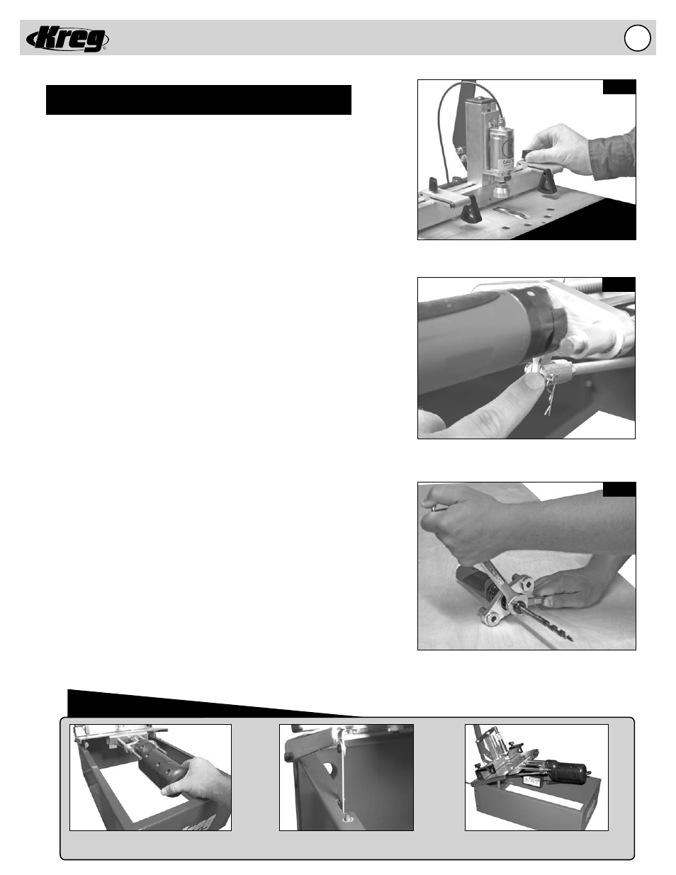
16.
Adjust the Swing Stop to locate the material
for repetitive drilling.
Disconnect the Connecting Rod to remove the
Air Drill Motor from the Guide Rods.
Loosen or tighten the collet with 9/16” & 3/4”
open ended wrenches.
Fig. 12A
Fig. 12B
Fig. 12C
Push motor in and lift assembly up
until latch catches on left of machine.
Tip
This latch will automatically catch
and hold assembly in place.
This will allow you to perform
maintenance easily on your machine.
Semi-Automatic Pneumatic Foreman DB55 Operation
ADJUSTMENTS (Cont’)
Swing Stops
(Fig. 12A)
Two Swing Stops are provided to assist in drilling pocket holes in the same
location on multiple work pieces of the same dimension. When the Swing
Stop is not used, it will pivot out of the way to allow the work piece to slide
underneath and rest against the fence. To change the location of the Swing
Stop simply loosen the knob, move to the new location and tighten the Knob
to lock the Swing Stop in position.
Changing the Drill Bit
(Fig. 12B & 12C)
IMPORTANT! Before changing the Drill Bit, make certain your machine
is DISCONNECTED from the AIR SUPPLY. Cycle the machine via the
Handle to remove air from the system. Without an air supply you can be
certain the Drill Bit will not accidentally engage while you are performing
this adjustment. While the air supply line is disconnected from the Air Motor
pressurized air with lubricating oil will be vented inside the cabinet if the
handle is accidentally moved to the operating position unless the machine
is DISCONNECTED from the AIR SUPPLY.
1. Disconnect the machine from the air supply.
2. Remove the Black Acrylic Top to gain access to the inside of
the machine.
3. Disconnect the air supply line from the Air Motor by pushing in the collar
on the inlet fi tting of the Air Motor and simultaneously pull out the tubing.
4. Lift the Tool Plate as it pivots on the hinges till the Safety Latch
engages to hold the Tool Plate in position.
5. Remove the Clevis and Cotter Pin from the Connecting Rod to
disconnect the Connecting Rod from the Drill Motor Mounting Block.
6. Remove the Drill Motor and Motor Mount assembly.
NOTE: Now is a good time to clean and lubricate the Guide Rods
according to the “MAINTENANCE” section of this manual.
7. Use 9/16” and 3/4” open ended wrenches to loosen the Collet.
Remove the dull Drill Bit from the Collet.
8. Insert a new or re-sharpened Drill Bit into the Collet, be sure to
fully insert the bit until it comes to rest at the bottom of the collet.
9. Use 9/16” and 3/4” open ended wrenches to tighten the Collet.
10. Re-install the Drill Motor and Motor Mount assembly on the Guide Rods.
11. Connect the Clevis and Cotter Pin through the Connecting Rod
and Drill Motor Mounting Block.
12. Lift the Tool Plate to disengage the Safety Latch and lower the
Tool Plate into position.
13. Make sure the air supply line for the Air Motor is free of debris
then connect the air supply line to the Air Motor by pushing in the
tubing until it seats in the inlet fi tting of the Air Motor.
14. Check the Drill Bit Depth Stop settings for the material thickness
being drilled.
15. Place the Black Acrylic Top back on the machine.