Db110 electric - adjustments – Kreg DB55 Pneumatic Foreman Pocket-Hole Machine User Manual
Page 13
R
DB110 Electric - Adjustments
12.
Adjust the Swing Stop to locate the material
for repetitive drilling.
Fig. 8A
The Drill Bit is held in position with set-screws
in the Drill Adapter.
Fig. 8B
Fig. 8C
Disconnect the Connecting Rod to remove the
Electric Drill Motor from the Guide Rods.
Push motor in slightly and lift assembly up
until latch catches on left side of machine.
Tip
This latch will automatically catch
and hold assembly in place.
This will allow you to perform
maintenance easily on your machine.
Semi-Automatic Electric Foreman DB110 Operation
ADJUSTMENTS (Cont’)
Swing Stops
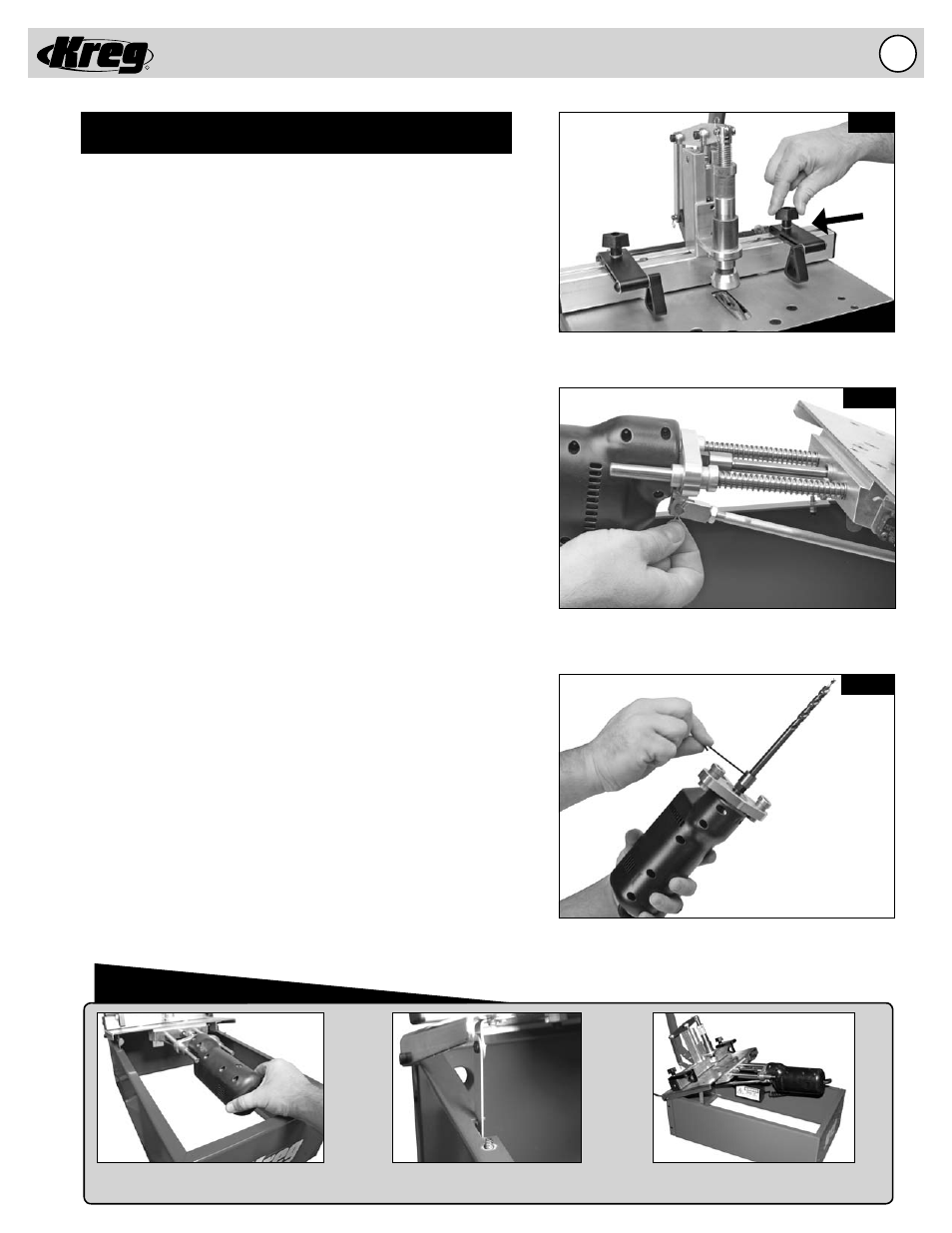
(Fig. 8A)
Two Swing Stops are provided to assist in drilling pocket holes in
the same location on multiple workpieces of the same dimension.
When the Swing Stop is not used, it will pivot out of the way to
allow the workpiece to slide underneath and rest against the fence.
To change the location of the Swing Stop simply loosen the knob,
move to the new location and tighten the knob to lock the Swing
Stop in position.
Changing the Drill Bit
(Fig. 8B & 8C)
IMPORTANT! Before changing the Drill Bit, make certain your
machine is DISCONNECTED from the ELECTRICAL SUPPLY.
Without an electrical supply you can be certain the Drill Bit will not
accidentally engage while you are performing this adjustment.
1. Disconnect the machine from the electrical supply.
2. Remove the Black Acrylic Top to gain access to the inside
of the machine.
3. Lift the Tool Plate as it pivots on the hinges till the Safety Latch
engages to hold the Tool Plate in position.
4. Remove the Clevis and Cotter Pin from the Connecting Rod to
disconnect the Connecting Rod from the Motor Mount.
5. Remove the Drill Motor and Motor Mount assembly.
NOTE: Now is a good time to clean and lubricate the Guide
Rods according to the “MAINTENANCE” section of this manual.
6. Loosen both Set-screws with the hex key that hold the Drill Bit
in place inside the Dill Adapter.
7. Insert a new or re-sharpened Drill Bit into the Drill Adapter,
aligning
the
fl ats on the Drill Bit shank with the set-screws in
the
Drill
Adapter.
8. Tighten the set-screws front and back to maintain equal
pressure on the Drill Bit shaft.
9. Re-install the Drill Motor and Motor Mount assembly on the
Guide
Rods.
10. Connect the Clevis and Cotter Pin through the Connecting
Rod and Motor Mount.
11. Lift the Tool Plate to disengage the Safety Latch and lower the
Tool Plate into position.
12. Check the Drill Bit Depth Stop settings for the material
thickness being drilled.
13. Place the Black Acrylic Top back on the machine.