LSC Lighting e24V3 User Manual
Page 10
E24V3 QUICK TOUR
e24 Dimming System
Operator Manual V3.0
Page 6
LSC Lighting Systems (Aust) Pty. Ltd
3.1.2 Indicators
The indicators located around the touch screen
are multi coloured and light or flash to indicate
their current condition as described below;
STATUS
• Green = Normal operation.
• Red (flashing) = Alarm. See status
message on LCD screen.
• Red (steady) = Alarm is acknowledged
but the problem still exists.
DMX
• Green = Valid DMX control signal.
• Green (flashing) = Loss of DMX signal.
• Red (flashing) = Error on DMX signal.
LSCnet
• Green = Valid LSCnet control signal
connected (from ePlates).
• Green (flashing) = Data traffic detected
on LSCnet.
CHANNEL LEVEL indicators
• Green = The channel is ON via DMX
control.
• Red = The channel is ON via memory
(ePlate) or channel test control.
The brightness of the channel indicator is
proportional to the channel level.
See the, “Maintenance and Alarms” section for
further details on alarms.
3.1.3 Touch Screen
The touch screen may be operated by touching
the virtual buttons with your finger. The home
page of the touch screen shows the current level
of each dimmer channel in a bar graph display.
If the e24V3 has been “locked”, the [Menu]
button is replaced by the [Unlock] button.
Touching the [Unlock] button and entering your
code number unlocks the e24V3 and reveals the
[Menu] button.
Pressing [Menu] allows you to access a range of
functions, setups and tests via sub-menus. Each
sub-menu screen has help information in the top
left corner. The menus are fully described in
Section 6 “Menu System”.
At the top of the screen is the name of this e24
dimmer. The default name is “e24 Dimmer” but
you can enter a name of your choice from the
options menu. Names are useful in identifying
each e24 dimmer in installations containing
more than one e24 and can also be used by the
“Houston” monitoring software.
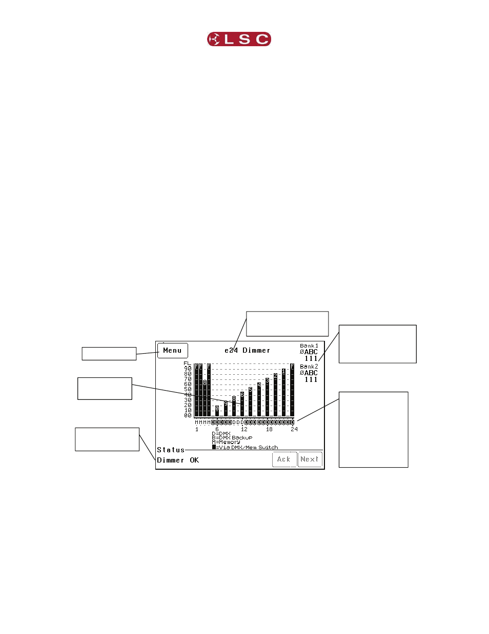
e24V3 Main Screen
The middle of the screen is a bar-graph display
of the channel levels with channels numbers 1 to
24 shown across the bottom. The levels from 00
to FL (Full) are shown on the left scale in
increments of ten, whilst the units of each
channel are shown on the individual channel
bars. In the example above, channel 3 has a
level of 68.
3.2 e24V3 Control Philosophy
The control source for each e24V3 dimmer
channel can be individually configured to control
that channel from either DMX, Memory or
Switch (DMX/Mem Switch).
3.2.1 DMX.
When configured for “DMX” a dimmer channel is
controlled from a DMX lighting controller. If DMX
fails, the DMX levels can be held indefinitely or
the channels can fade to a “DMX Backup”
memory previously stored in the e24V3. If the
Letter shows
current control
source for each
channel as per
legend on screen.
White text on black
shows control
source is via the
DMX/MEM Switch.
Status of Power Phases
A, B & C to each bank.
1 = Present
0 = Not Present
Menu button
Scrolling Status
Messages
Programmable Dimmer
Name