LSC Lighting e24V3 User Manual
Page 34
e24 Dimming System
Operator Manual V3.0
Page 30
LSC Lighting Systems (Aust) Pty. Ltd
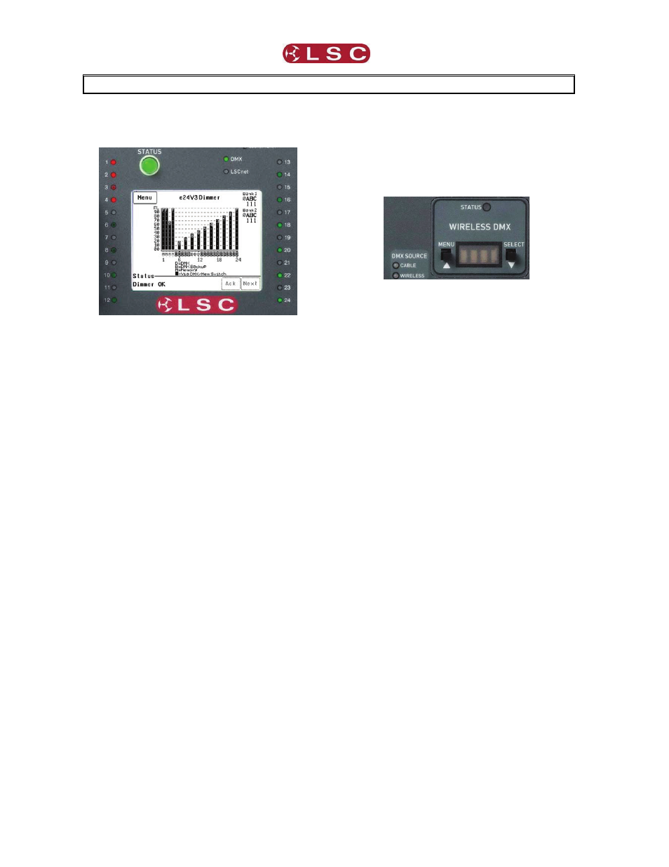
8 INDICATORS, ALARMS & TROUBLESHOOTING
Warning. No user controls or user serviceable
parts are located inside the e24V3 Dimmer.
Refer all servicing to suitably qualified
personnel.
If the e24V3 is not functioning correctly, check
the LED indicators on the front panel and the
status area at the bottom of the LCD screen for
any messages.
8.1 Status LED
• Green =
Normal
operation.
• Red (flashing) = Alarm. See message
on LCD touch screen.
• Red (steady) = Alarm is acknowledged
but the problem still exists.
Possible causes of a flashing Status LED are;
• Over Temperature.
If the temperature of the e24V3 is too
high, the circuitry automatically switches off the
dimmers. All dimmer channels will flash red.
Either reduce the load or increase the cooling to
the e24V3. When the temperature returns to
normal, the e24V3 automatically returns to
normal operation.
• Temperature sensor failure.
If the temperature sensor fails, the
circuitry automatically switches off the dimmers.
All affected dimmer channels will flash red.
• Loss of input power phase(s).
If any of the input power phases are lost,
the affected dimmer channel LEDS will flash red.
In the event of any alarm, read the message on
the status area of the LCD screen. Press [Ack]
on the touch screen to acknowledge the alarm.
This stops the status LED from flashing but it
remains red until the fault condition is rectified.
8.2 DMX LED
• Green = Valid DMX control signal
connected.
• Red (flashing) = Error on DMX control
signal.
• Green (flashing) = Loss of DMX control
signal.
8.3 LSCnet LED
• Green = Valid LSCnet control signal
connected (from ePlates).
• Green (flashing) = Data traffic detected
on LSCnet.
8.4 DMX Source
If your e24V3 is fitted with the Wireless DMX
option, the LED’s beside the Wireless DMX
panel show the DMX source that is controlling
the dimmers.
If both cable and wireless DMX are available,
the e24V3 will automatically use the cable DMX.
Cable LED
• Green = Cable DMX Data in use.
Wireless LED
• Green = Wireless DMX Data in use.
• Orange = Wireless DMX Data available
but not in use.
8.5 Channel LEDs
The numbered LED’s around the perimeter of
the control panel light when their respective
dimmer channel is on. The brightness of the
LED shows the channel level.
• They
light
green
when under DMX
control.
• They
light
red
when under local control.
If a dimmer channel is not working check the
MCB (Miniature Circuit Breaker) for that dimmer
channel.
8.6 Circuit Breakers
If the MCB has tripped (OFF), firstly try to
determine the cause of the breaker tripping. It
could be a blown lamp or a circuit overload.
Rectify to problem (replace the lamp or reduce
the load) then restore the MCB. If the MCB
continues to trip, refer the problem to a suitably
qualified person.
If the MCB has not tripped, you can test the
operation of the dimmer from the local LCD
touch screen. See section 6.2.2 “Channel Test”
for details. If the dimmer is working from the
touch screen but not via DMX, check that the
dimmer is patched to the correct DMX slot and
configured for the correct “control source”.