3 e24v3 quick tour – LSC Lighting e24V3 User Manual
Page 9
e24 Dimmer
Operator Manual V3.0
LSC Lighting Systems (Aust) Pty. Ltd
Page 5
3 e24V3 QUICK TOUR
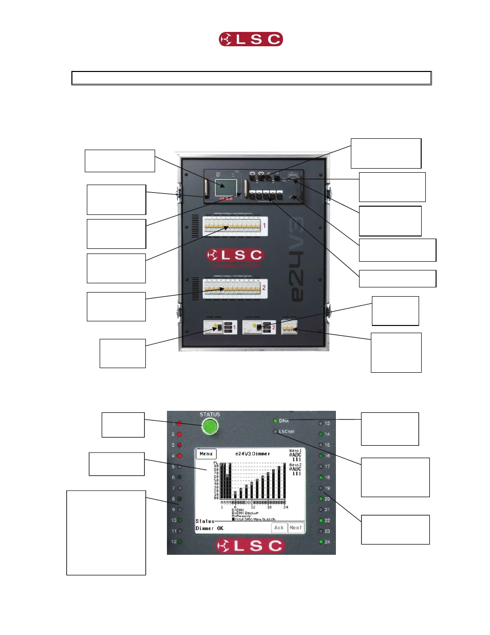
3.1 Front Panel
The front panel contains the Input circuit breakers, load MCB (Miniature Circuit Breakers), control panel
that includes the status indicators and LCD touch screen and the DMX and LSCnet connectors and
terminate switches plus the 5 DMX splitter outputs and optional wireless DMX.
3.1.1 Control Panel
The Control Panel contains the indicators for status and channel levels and the LCD touch screen.
e24V3 Control Panel.
LCD Touch Screen
Control Panel
LSCnet input,
output & Terminate
switch
Bank 1 MCB’s
(Load Circuit
Breakers)
Dimmer Channel level
indicators 1 to 12.
Brightness indicates
channel level.
Green = Controlled by
DMX
Red = Controlled by
Memory
LCD Touch
Screen
Status
Indicator
DMX Remote
Control Status
Indicator
LSCnet
(ePlate) Remote
Control Status
Indicator
DMX input,
DMX Thru and
Terminate switch
Bank 1
Channel Level
indicators
Bank 2 MCB’s
(Load Circuit
Breakers)
Bank 2
Channel Level
indicators
Bank 1
Input RCD
Breaker
Bank 2
Input RCD
Breaker
3 Auxiliary
Outputs
RCD
Breakers
Dimmer Channel
level indicators
13 to 24
Programming port for
software upgrades
5-way DMX splitter
Wireless DMX
receiver option
(if fitted).