29 cv valve actuator wiring, In cv valve actuator wiring, Age 29 – Nortec SE Series User Manual
Page 32: Cv valve actuator wiring
29 | Installation
Figure 31: Outdoor Temperature Setback (On/Off Control)
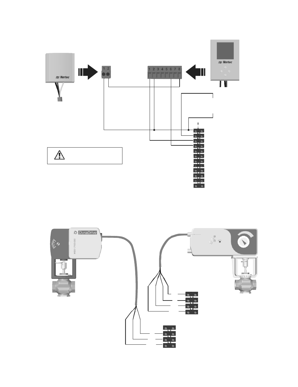
CV Valve Actuator Wiring
Figure 32: CV Valve Actuator Wiring
9 - Ground
10 - Actuator 24 VAC
11 - Actuator Ground
12 - 0-10 VDC Out
Y/Bk
Gr
Note: 1 Wire the CV valve actuator
to the humidifier’s low voltage
terminal strip.
2 Use minimum of 18 AWG wire
and keep as short as possible.
3 After installation and powering
humidifier verify that travel of
actuator at full demand is to the
fully open position.
SE 1050 low
voltage terminal strip
Bk
R
9 - Ground
10 - Actuator 24 VAC
11 - Actuator Ground
12 - 0-10 VDC Out
Y/Bk
Bk
R
SE 50 - 750
Actuator
SE 1050
Actuator
SE 50 - 750 Terminal Strip
1
-
G
ro
u
n
d
2
-
2
4
V
A
C
6
-
A
n
a
lo
g
O
u
t
8
-
T
e
m
p
e
ra
tu
re
1510142 - Digital Wall Humidistat or,
2520266 - Digital Duct Humidistat Package
1
-
2
4
V
A
C
2
-
T
e
m
p
e
ra
tu
re
Insert On/Off
controls or jumper
between 1 and 2
2520263 - Outdoor Temperature
Sensor
Connect 24 VAC, terminal
1 of SE to terminal
2 of controllers.
Note:
1
2
The Temperature sensor is
intended for duct mounting.
Locate the temperature sensor
near the fresh air intake. This
will ensure accurate representation
of the outdoor air temperature.
E
X
T
S
E
1- 24 VAC
2 - On/Off Loop
3 - Ground
4 - Control Signal
5 - Limit Signal (SETC only)
6 - 5 VDC
7 - Ground
8 - Full Tank Blow Down
9 - Ground
10 -
11 - Actuator power
12 -
Actuator power
0-10 VDC Out