D on/off or modulating control (j10), Age 61, On/off or modulating control (j10) – Nortec SE Series User Manual
Page 64: Sep model (j11 to j13), Full tank blowdown (j14 and j15), Modulation offset (j16)
61 | Operation
On/Off or Modulating Control (J10)
The SEP’s output can be controlled by either an On/Off humidistat or a modulating humidistat.
To set the SEP to operate with a modulating humidistat remove Jumper J10. (Factory setting =
jumper removed, modulating operation)
J10 Removed– Modulating operation, the controller monitors the demand signal on
terminal point 4 of the control terminal strip and adjusts humidifier output to match it.
J10 Installed - The SEP is configured for On/Off operation. The controller will ignore any
modulating signals even if they are connected.
SEP Model (J11 to J13)
The SEP model is configured using Jumper 11 to 13. The jumper setting is configured at the
factory and should not be adjusted in the field.
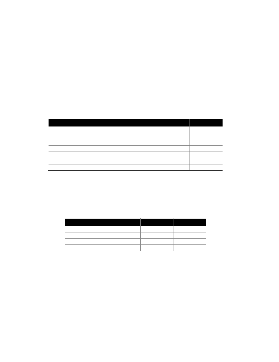
Table 8: SEP Model Configuration
Resulting Control
J11
J12
J13
SEP 50/100
0
0
0
SEP 175
1
0
0
SEP 250
0
1
0
SEP 375
1
1
0
SEP 525
0
0
1
SEP 750
1
0
1
SEP 1050
1
1
1
Full Tank Blowdown (J14 and J15)
The SEP can be configured to periodically drain the tank to help flush minerals and scale.
Jumpers 14 and 15 control blowdown frequency. Hours are accumulated on a weighted basis (1
hour at 50% demand = 0.5 hrs). (Default = J14 and J15 installed, no full tank blowdown)
Table 9: Full Tank Blowdown Jumper Configuration
Resulting Control
J14
J15
No Full Tank Blowdown
1
1
96 hours between FTBD
0
0
48 hours between FTBD
1
0
24 hours between FTBD
0
1
Modulation Offset (J16)
The SEP controller can be configured to work with a modulating humidistat with 4-20 mA or 2-
10 VDC output. Modulation offset can be configured with jumper 16. (Factory setting = Jumper
removed, 0-10 VDC or 0-20 mA control signal)
J16 Removed – Controller is configured for a 0-10 VDC or 0-20 mA control signal.
J16 Installed – Controller is configured for a 2-10 VDC or 4-20 mA control signal.
Note: For mA control a 500
resister is required between terminals 3 and 4 on the low voltage
control terminal.