Dce to dsu data and clock/timing signals, Dce to dsu data and clock/timing signals -2, Figure 7-3 send data (sd) and receive data (rd) – Verilink DIU 2130 (880-503297-001) Product Manual User Manual
Page 82
DIU/DIM Details
7-2
Verilink
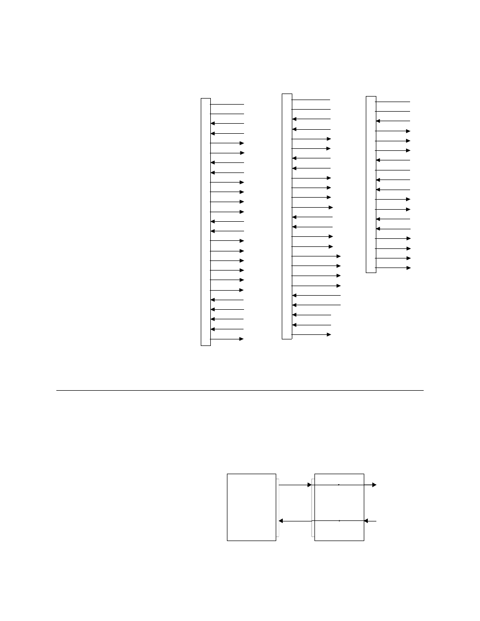
Figure 7-2 DIU 2130 Data Signal Connections
DCE to DSU Data and Clock/Timing Signals
At the DCE interface on the DIU, data from the equipment being
sent towards the network is referred to as Send Data (SD). Data
from the network being sent towards the equipment is referred to
as Receive Data (RD) (Figure 7-3).
Figure 7-3 Send Data (SD) and Receive Data (RD)
SIG GND
SD (+)
SD (-)
RD (+)
RD (-)
DC-37
Female
TO DIM 2449
(DCE)
LL
RL
TM
RS (+)
RS (-)
CS (+)
CS (-)
DM (+)
DM (-)
TR (+)
TR (-)
RR (+)
RR (-)
ST (+)
ST (-)
RT (+)
RT (-)
TT (+)
TT (-)
CHAS GND
1
19
4
22
6
24
7
25
9
27
11
29
12
30
13
31
5
23
18
14
10
35
17
26
8
RS-449/422
SIG GND
TD (+)
TD (-)
RD (+)
RD (-)
DB-25
Female
TO DIM 2530
(DCE)
LL
RL
TI
1
7
2
14
3
16
4
19
5
13
6
22
20
23
8
10
15
12
25
21
18
11
24
9
17
RTS (+)
RTS (-)
CTS (+)
CTS (-)
DSR (+)
DSR (-)
DTR (+)
DTR (-)
DCD (+)
DCD (-)
TSET DCE (+)
TSET DCE (-)
TSET DTE (+)
TSET DTE (-)
CHAS GND
RSET DCE (+)
RSET DCE (-)
(BA)
(BA)
(BB)
(BB)
(CA)
(CA)
(CB)
(CB)
(CC)
(CC)
(CD)
(CD)
(CF)
(CF)
(DB)
(DB)
(DD)
(DD)
(DA)
(DA)
EIA 530
CHAS GND
SIG GND
DSR
RLSD
DTR
LT
SD (+)
SD (-)
RD (+)
RD (-)
SCTE (+)
SCTE (-)
SCR (+)
SCR (-)
SCT (+)
SCT (-)
A
B
C
D
E
F
H
K
P
S
R
T
U
W
V
X
Y
a
TO DIM 2035
(DCE)
34-PIN
Female
RTS
CTS
V.35
Customer
Equipment
(DTE)
SD
RD
T1 XMT
T1 RCV
DSU
(DCE)