T1 multiplexer mode -15 data equipment timing -15, T1 multiplexer mode, Data equipment timing – Verilink DIU 2130 (880-503297-001) Product Manual User Manual
Page 95
DIU/DIM Details
Verilink
7-15
T1 Multiplexer
Mode
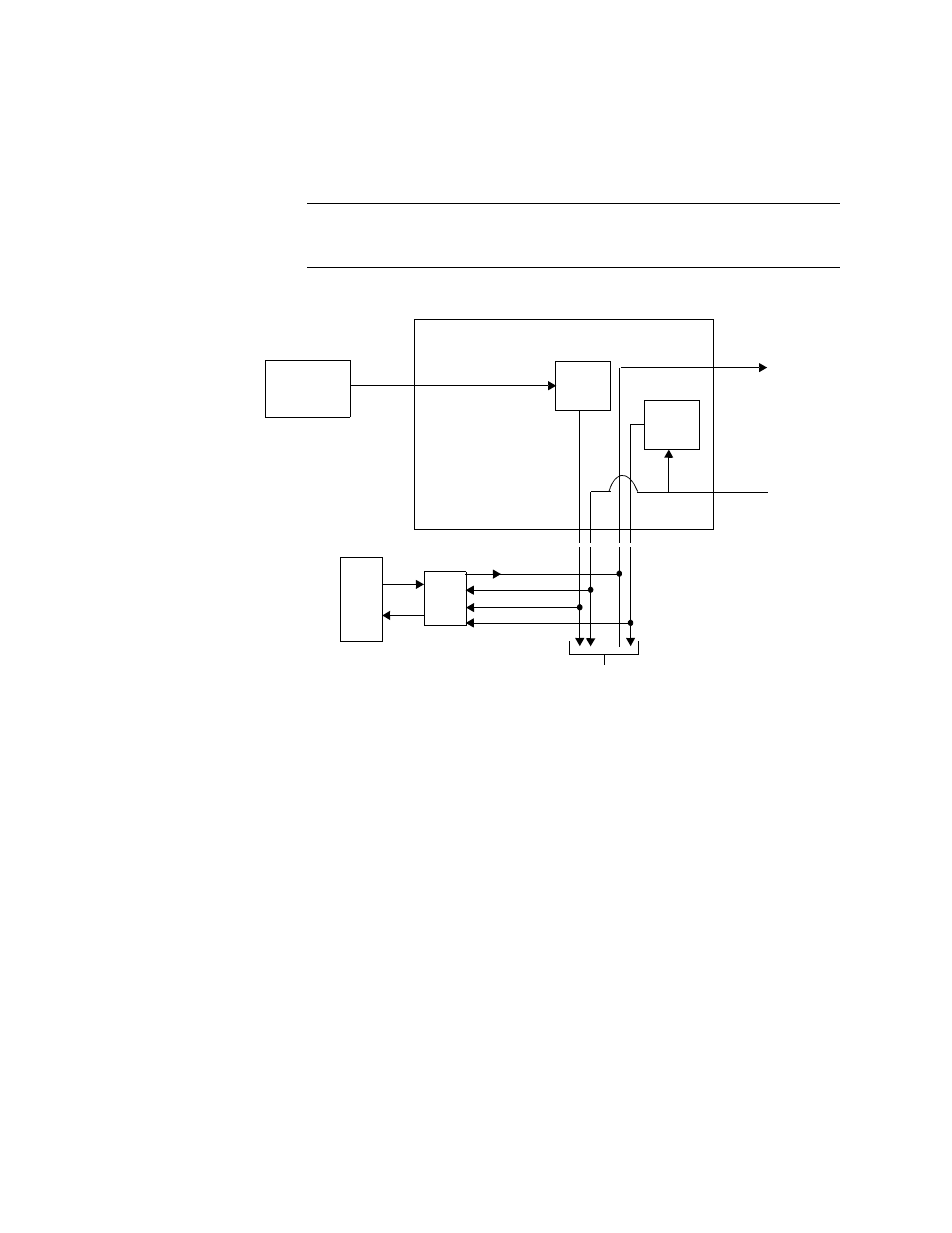
Figure 7-17 shows an external timing application when the CSU is in
the T1 multiplexer mode. The external clock is applied directly to
the NCC or TAC. This clock is a stable 1.544 MHz signal in an RS-
422 or TTL format.
NOTE: The external clock must meet the input frequency, jitter, and
wander requirements of a DS1 signal as per AT&T PUB
62411.
Figure 7-17 External Timing (T1 Multiplexer Mode)
Data Equipment
Timing
In data equipment timing, the clock source is the TT (Terminal
Timing) signal applied from a data equipment device in a DTE
configuration to a DIU 2130. Figure 7-18 shows data equipment
timing for the CSU T1 multiplexer mode of operation. Data Bus A or
B conveys the data between the DIUs and CSU, and Data Bus C
conveys the TT signal.
EXTERNAL
CLOCK
DATA
EQPT
DIU
TO/FROM OTHER DIUs
XMT DATA
RCV DATA
XMT CLOCK
RCV CLOCK
DATA BUS A, B, or C
TO/FROM
NETWORK
REFERENCE
CLOCK
NCC or TAC
RS-422 or
TTL
TRANSMIT
CLOCK
RECEIVE