Technical description, Technical description -4, The hdm 2182 consists of two components – Verilink HDM 2182 (880-502925-001) Product Manual User Manual
Page 12
HDM 2182 DS3 DSU Overview
1-4
Verilink HDM 2182 User Manual
•
The HDM can be managed with a graphical user interface (GUI)
using Verilink’s Node Manager software application.
Technical Description
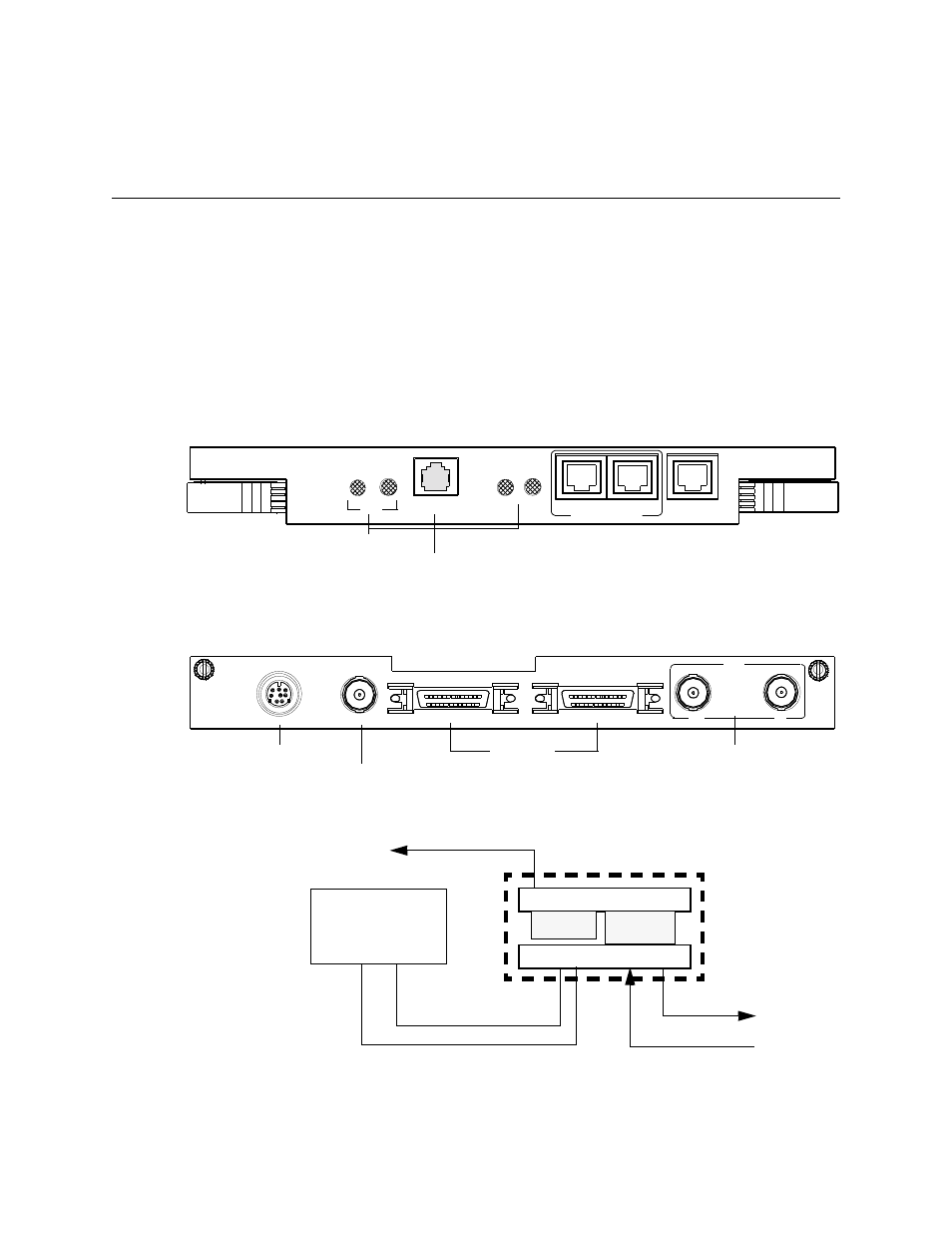
The HDM 2182 consists of two components:
•
A front-panel module, which contains the DSU microprocessor
including firmware in flash, and
•
A detachable rear-panel connector interface module (CDM
2182), which contains two high-speed serial interface (HSSI)
data ports and 75
Ω
coaxial transmit and receive network
connectors for the DS3 network interface.
Figure 1-2 HDM 2182 Front Panel
Figure 1-3 CDM 2182 Rear Panel
Figure 1-4 Functional Block Diagram of HDM 2182 Components
HDM
2182
LOCAL
SYS
MANAGEMENT
PRI
EXT
SNMP
NE
T
ASCII Interface port
LEDs
A
B
PORT
EXT TIMING
INPUT
3
1
1-10
1876-001
HSSI
DS3
RX
TX
2
182
CDM
T1 TIMING
INPUT
75
Ω
BNC female
75
Ω
BNC female
HSSI ports
8-pin female circular DIN
HSSI
DATA B
DATA A
(DISABLED)
AS2000 shelf
128-pin
HDM 2182
connector
CDM 2182
Shelf
midplane
Customer
To SNMP Manager
TX DS3 Net
applicatio
FRONT
BACK
HSSI
10BaseT
RX DS3 Net
75
Ω
coaxial connection