Components, Front module, Components -3 – Verilink QUAD DATA (880-503319-001) Product Manual User Manual
Page 11: Front module -3
Overview
Verilink QUAD DATA User Manual
1-3
Components
A complete QUAD DATA installation consists of the QUAD DATA
front module and a DIM 3030 rear connector module.
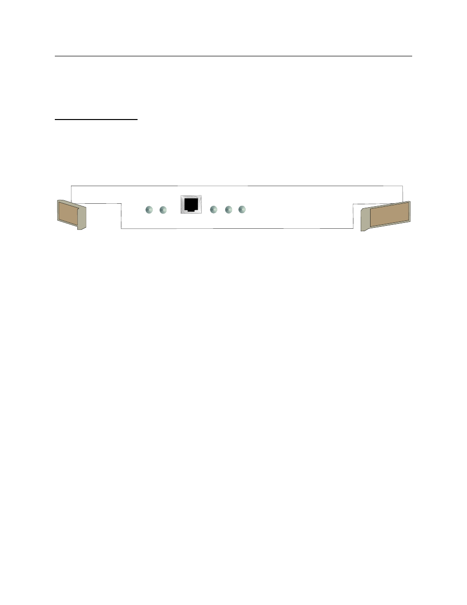
Front Module
The front panel of the QUAD DATA module has an RJ-11 modular
Craft interface (ASCII terminal) port and 5 tri-color Light Emitting
Diodes (LEDs) which give status indications.
Figure 1-1 QUAD DATA Front Panel
SYS LED
The SYS LED indicates the status of the QUAD DATA module. When
the module is receiving normal power from the shelf power
supplies, the SYS LED should be lit steady green.
During the process of power-up the SYS LED will be briefly amber
as it negotiates with other modules for shelf controller status.
If the SYS LED is not lit, the QUAD DATA module has no power or it
is defective.
Data Port LEDs
Each data port of the QUAD DATA module has an LED on the front
panel as a status indicator.
Power-Up Sequence
During module initialization the front panel LEDs change state
rapidly. First they will be all red, then all off except port 4 red,
then a rapid countdown of red flashes from port 4 to port 1, then
port 2 flashes orange three times. After a pattern of flashing green
LEDs, they all flash green, then red, then go out for two seconds.
Once the module has completed the initialization self-test, the SYS
LED will remain amber momentarily as the module negotiates shelf
controller status.
QUAD
DATA
SYS
LOCAL
DATA
DATA
1
2
3
4