Timing menu, Timing menu -8, Figure 3-5 – Verilink QUAD DATA (880-503319-001) Product Manual User Manual
Page 32: Crossover cable dce, No connection, Device
Configuration
3-8
Verilink QUAD DATA User Manual
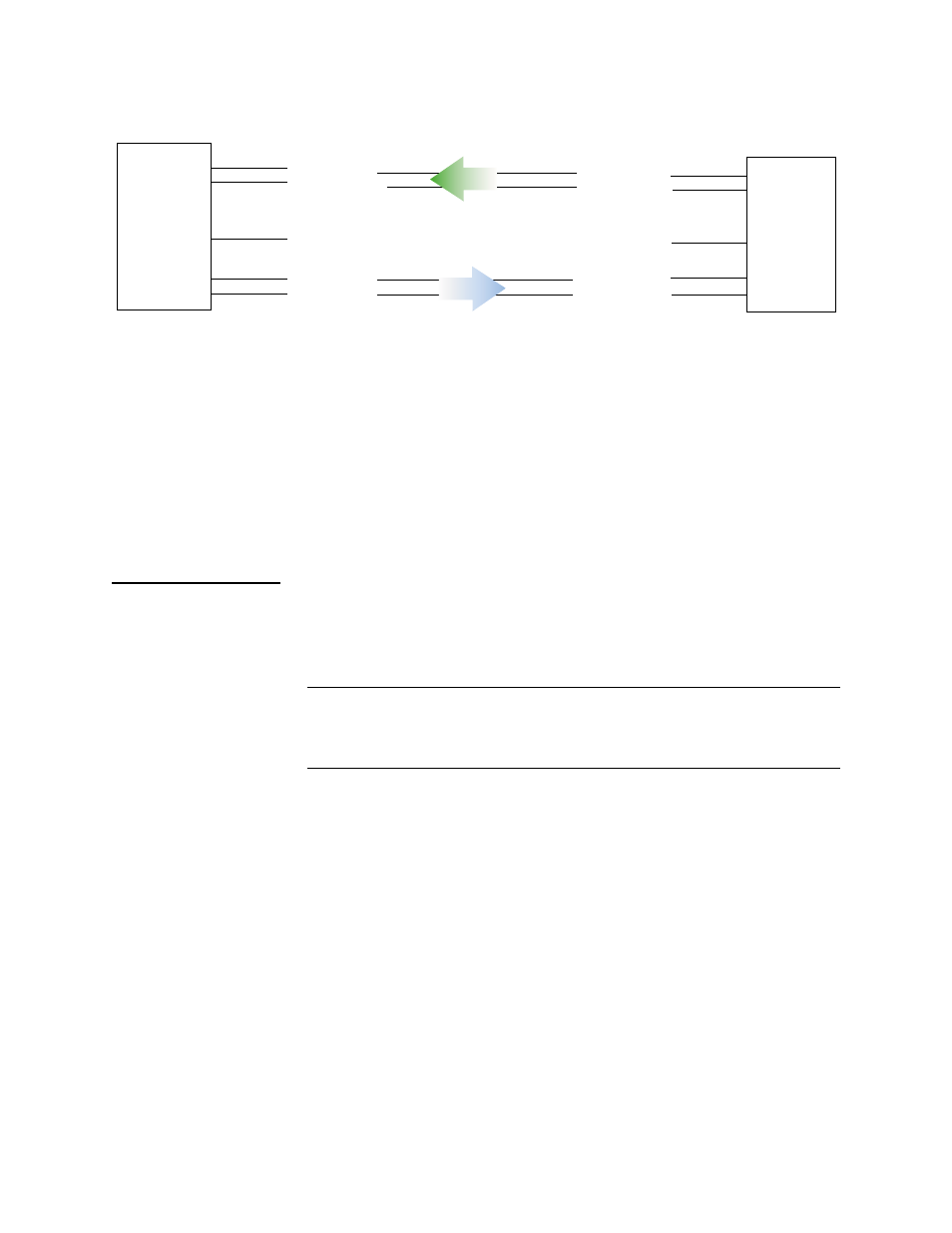
Figure 3-5 Crossover Cable
If the network design requires the QUAD DATA port to be part of a
tail circuit, accepting timing from a DCE device—there are two
methods available:
•
Use a straight through cable to connect the DCE to the QUAD
DATA port, put the port in DTE mode, and set the port to be
the shelf timing source (see the section “
”).
•
Use a crossover cable to connect the DCE to the QUAD DATA
port, put the port in DCE mode, set the clock selection to TT,
and set the port to be the shelf timing source (see the section
“
”).
Timing Menu
The SCM maintains a timing table for all of the modules in each
shelf of a node. This table determines the transmit clock source for
each QUAD DATA module in the shelf, as well as all T1 network
modules.
NOTE: Any QUAD DATA port configured for DTE mode must provide
clock for the shelf. Each shelf may have only one active clock
source. Therefore all QUAD DATA ports set for DTE mode in
any shelf must be connected to the same clock source.
The Timing Menu is accessed by using the T command on the
QUAD DATA Configuration Menu. See
.
Quad
Data
Module
DCE
Mode
Receive Data
Transmit Data
Receive Clock
Transmit Clock
Crossover Cable
DCE
Transmit Data
Terminal Timing
No Connection
Terminal Timing
Transmit Clock
Receive Data
Device
Receive Clock