Telco cloud – Verilink QUAD DATA (880-503319-001) Product Manual User Manual
Page 31
Configuration
Verilink QUAD DATA User Manual
3-7
pair). In a synchronous interface there must always be a clock
related to each datastream. When in DTE mode, the QUAD DATA
module outputs a clock which is derived from the data arriving
from another location on the Terminal Timing pair (Serial Clock
Transmit External in V.35). The device connected to the QUAD
DATA module must use that clock (on TT or SCTE) to control its
sampling of Transmit Data.
NOTE: Because it has a simplified clock interface design (only one
pair of clock leads) DTE mode is not supported for the X.21
interface type.
When it is in DTE mode, the QUAD DATA module accepts
information which is to be sent to the WAN on the pair designated
Receive Data. The clock presented along with that data, on the
Receive Clock pair, must be used to control the transmission rate of
that data on to the WAN. If the clock on the Receive Pair does not
drive the transmit path, buffer over-runs and/or buffer under-runs
will occur leading to a loss of data. See
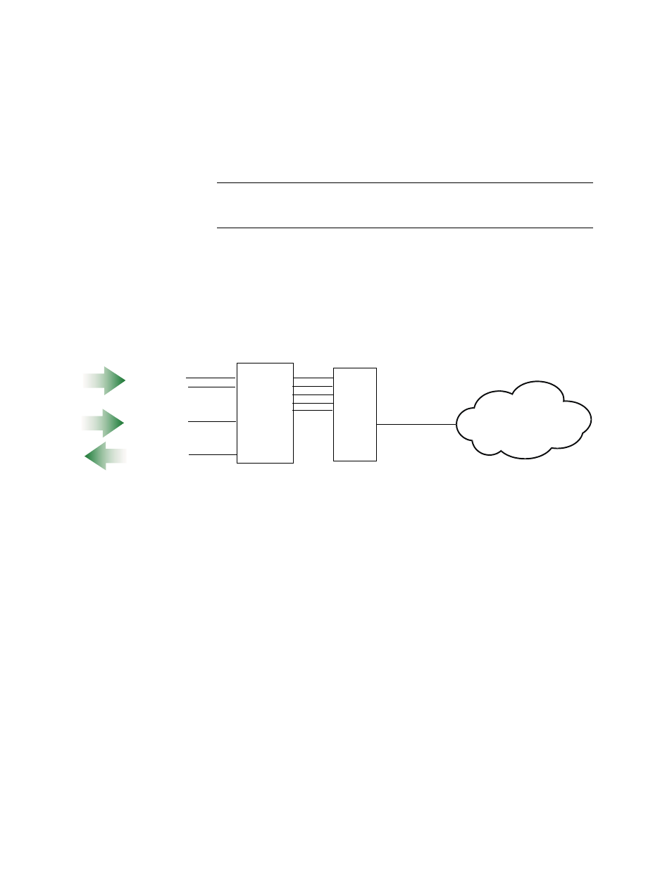
Figure 3-4 DTE Mode Signal Flow
Since the AS3000 shelf has a single timing source for all T1 network
ports, and since the device connected to a port set for DTE must
provide transmit clock, logic dictates that any QUAD DATA port
configured for DTE mode must provide the transmit clock for every
T1 network port in that shelf. This is likely to produce undesirable
complications in the network design.
Tail Circuit Timing
When connecting a QUAD DATA port to a DCE device, a crossover
cable can be used instead of putting the port in DTE mode. This
method allows the QUAD DATA port to be kept in DCE mode. In this
scenario, instead of the QUAD DATA port accepting a clock from
the external DCE device, the QUAD DATA port provides the clock.
The external DCE device must then use the clock provided by the
QUAD DATA module as its transmit timing source.
Summary
If the network design requires a QUAD DATA port to provide clock
to a tail circuit—use a crossover cable to connect the external DCE
and put the QUAD DATA port in DCE mode. See
Quad
Data
Module
CSU
or
T3
Mux
Telco
Cloud
DTE
Mode
Receive Data
Transmit Data
Receive Clock
Transmit Clock
In DTE mode, Receive Data and both clocks are inputs to
the Quad Data module