Westermo RM-455U-D User Manual
Page 48
Chapter Three
Configuration
Man_455U-D Rev 3.04
Page 49
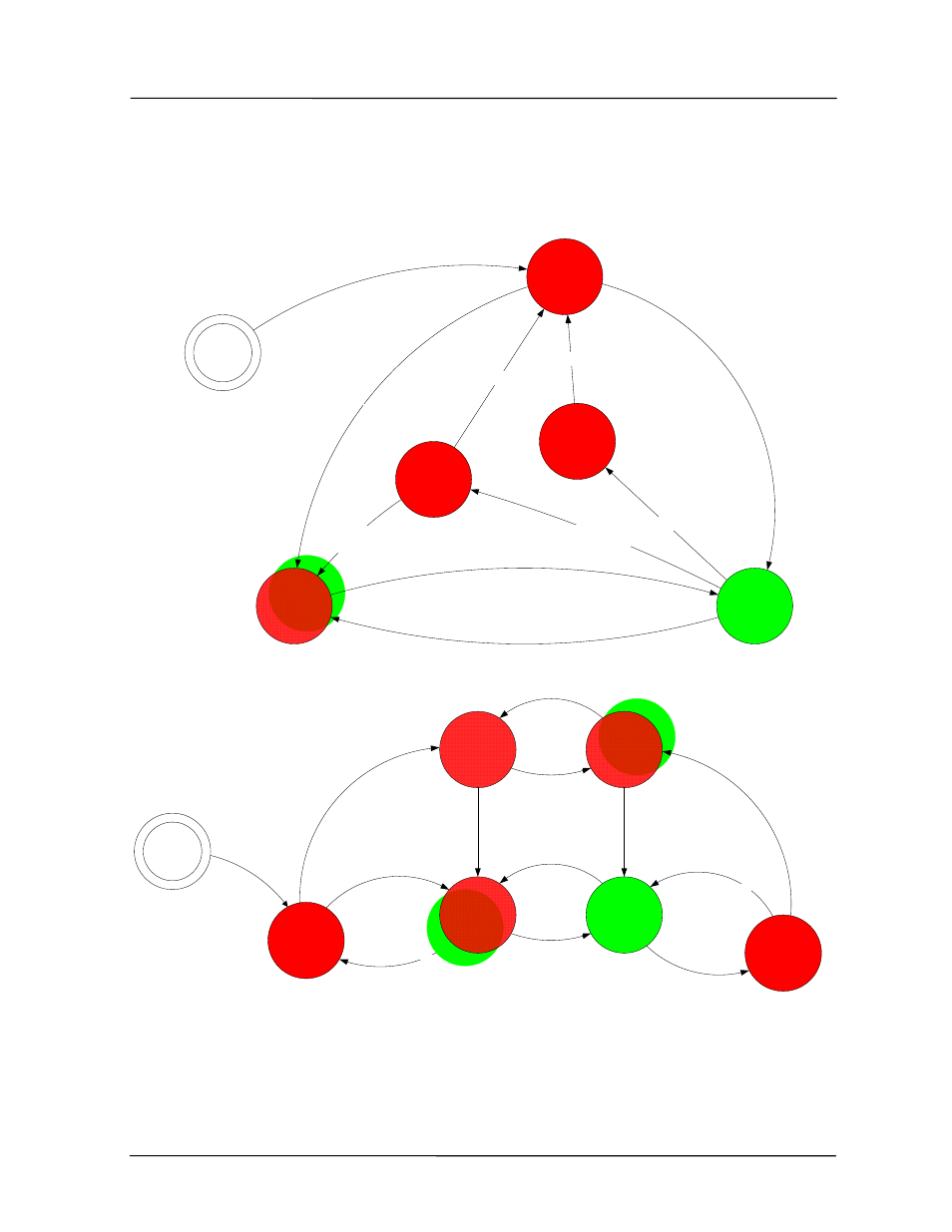
The following diagram shows the states of the dual redundant system, the relationship to the
AT#O commands, the OK LED state, and S-registers S33 and S11 (Firmware versions 3.03
and later).
Start
Get Control
S33=2
Active
S33=2
Active No
Secondary
S33=4
Standby
S33=5
Secondary Responding on
DIO
Fault cleared
Secondary Responding on
DIO
No Signal from
Secondary
E455U-D Dual Redundant
Control - Primary
AT#O3
No Signal from
Secondary
No Signal from
Secondary
Forced
Standby
S33=5
Radio Fault or
Low Battery
Timeout (S11)
AT#O5
Flash Red-Green
With DIO LED
E455U-D Dual Redundant
Control - Secondary
AT#O4
Start
Standby
S33=6
Active
S33=3
Primary Inactive
Activity on DIO
From Primary
Give Control
S33=6
Primary Inactive
Primary Active
Force
Changeover
S33=6
Primary Inactive
after timeout
(S11)
AT#O6
Primary Active
after timeout
(S11)
Flash Red-Green
With DIO LED
Standby
(Fault)
S33=6
Primary Inactive
Radio Fault or
Low battery
Fault cleared
Active
(Fault)
S33=3
Radio Fault or
Low battery
Fault cleared
Flash Red-Green
With DIO LED