Redundancy status – Westermo RM-455U-D User Manual
Page 49
455U-D Radio Modem
User Manual
Page 50 © May 2010
3.8.5 Firmware versions prior to 3.03
Firmware version 3.03 introduced enhanced diagnostics by flashing the OK LED in
synchronisation with the DIO LEDs. For firmware versions 3.00 to 3.02, refer to the following
diagrams indicating the LED diagnostics and Redundancy state diagrams.
LED Indicator
Redundancy Status
1½ sec on, ½ sec off.
Normal operation. Primary is active, Secondary is inactive but functional
1 second on, 1 second off
Secondary Fault. Primary is active, Secondary is inactive and has a fault
½ second on, 2 seconds off
Secondary is active, Primary is inactive and has a fault
Always On
Hardware fault on I/O Circuit or module fault - disconnect wire to
determine which module is functional.
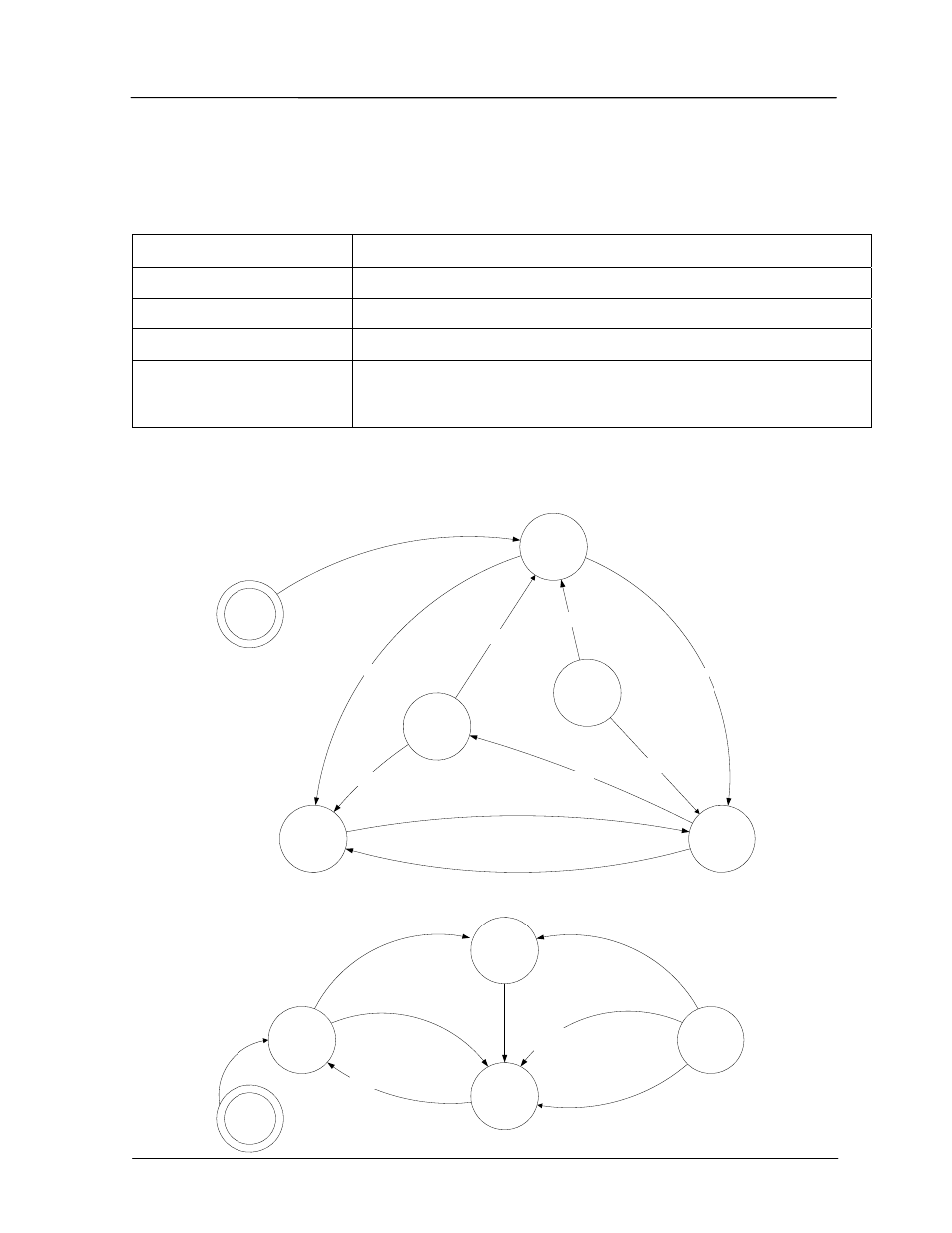
The following diagram shows the states of the dual redundant system and the relationship to
the AT#O commands, and S-registers S33 and S11 (Firmware versions 3.00 to 3.02).
Start
Get Control
S33=2
Active
S33=2
Active No
Secondary
S33=4
Standby
S33=5
Secondary Active
Fault cleared
Secondary Responding
Secondary Not Responding
E455U-D Dual Redundant
Control - Primary
AT#O3
E455U-D Dual Redundant
Control - Secondary
AT#O4
Start
Standby
S33=6
Active
S33=3
Primary Inactive
Activity From Primary
Give Control
S33=6
Primary Inactive
Primary Active
Secondary Inactive
Secondary Inactive
Force
Changeover
S33=6
Primary Inactive after timeout
(S11)
AT#O6
Primary Active
Forced
Standby
S33=5
Fault
Timeout (S11)
AT#O5