Carrier module, Fibre channel board (optional), System overview – Grass Valley K2 Summit 3G v.9.0 User Manual
Page 33: Status indicators, Front panel indicators, Power led, Carrier module fibre channel board (optional), System overview status indicators
Carrier module
The carrier module provides the functionality typically associated with a motherboard in a PC. It
hosts the CPU, one optional PCIe board, and provides rear panel connections for Gigabit Ethernet,
USB, VGA, and IEEE 1394a (Firewire). The IEEE 1394a port is for debugging purposes only. It
is not supported for customer use. Do not attempt to configure or otherwise use this port. The carrier
module also provides a GPI connection and connections for reference. It plugs into the midplane
board.
Related Topics
on page 99
Fibre Channel board (optional)
The optional PCIe Fibre Channel board is hosted by the carrier module.
Related Topics
Fibre Channel board (optional) removal
on page 100
System Overview
The K2 Summit 3G system is a PCIe bus-based Windows computer with extensive enhancements
to provide the video disk recorder functionality. This section explains the major architectural blocks.
Status indicators
The following sections describe the visual and audible indicators that communicate the current
operating status and system health of the K2 Summit 3G system.
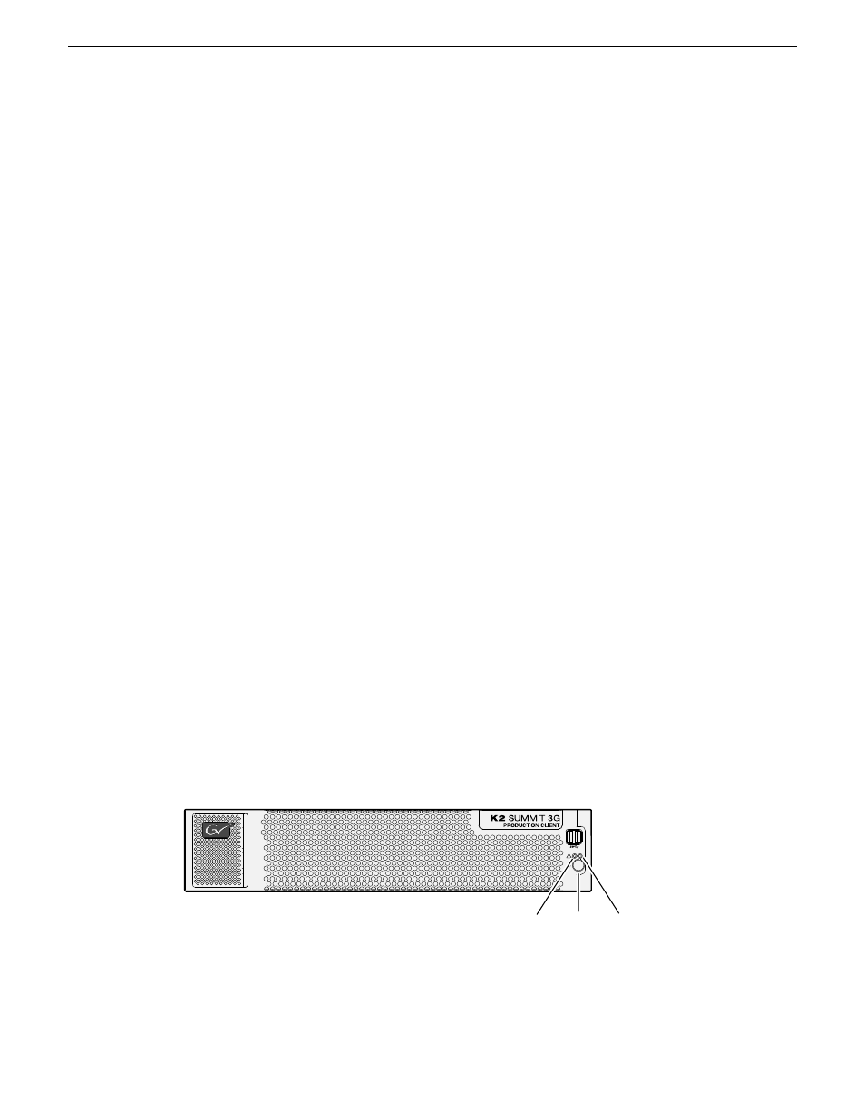
Front panel indicators
The front bezel assembly must be installed for front panel LEDs to provide status.
Power
LED
Standby
switch
Service
LED
Power LED
The Power LED indicates status as follows::
14 November 2012
K2 Summit 3G Service Manual
33
Product description