Configuring the system, Diagnostics window board recognition example – Grass Valley Profile Mix Effects Upgrad 100 Fibre Channel User Manual
Page 73
Advertising
Configuring the System
PDR 100 Fibre Channel Installation
73
.
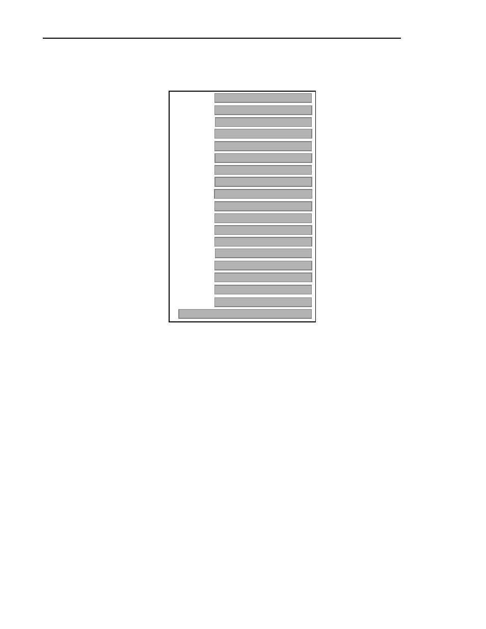
Figure 31. Diagnostics Window Board Recognition Example
Configuring the System
Configuring the system involves completion of the tasks listed below.
• System Set-up for Ethernet
• Configuring the Ethernet Board for TCP/IP
• Configuring the Fibre Channel Board
Slot J1
Slot J2
Slot J3
Slot J4
Slot J5
Slot J6
Slot J7
Slot J8
Slot J9
Slot J10
Slot J11
Slot J12
Slot J13
Slot J14
Slot J15
Slot J16
Slot J17
Mother Bd
Pentium CPU
Quit
Mother Board (Rev 0)
RS422, if installed
Ref Gen (4 LTC) (Rev 0)
Non-EISA slot
SMCA010
Slave EDR (Rev 0)
BUS4202
Serial Cmpnt I/O (Rev 2)
Audio
Fibrechannel I/F (Rev 0)
Master EDR (Rev 0)
Serial Cmpnt I/O (Rev 2)
Audio
Audio
Audio
Advertising