Grass Valley PDR 200 Service Manual User Manual
Page 102
Advertising
Chapter 6 Parts Removal and Replacement
6-10
PDR 200 Service Manual
4. Carefully move the front panel far enough away from the chassis to access the LED
cable.
5. Disconnect the LED cable connector (2 in Figure 6-6) which runs from the chassis to
the front panel and place the front panel face down on a flat level surface.
6. If necessary, use the Torx tool with the T15 tip to remove the gasket (3 in Figure6-6).
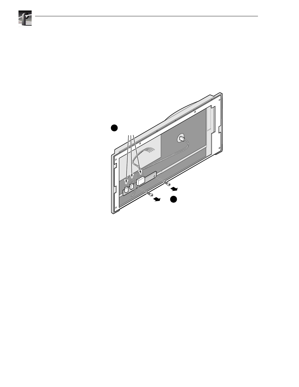
7. Disconnect all cables from the board (1 in Figure 6-7).
Figure 6-7. LED Board Removal
8. Use the Torx tool with the T10 tip to remove the screws which secure the board to the
panel (2 in Figure 6-7).
9675-20
1
Disconnect
cabling
2
Remove screws
and LED board
Advertising