Connector pin-outs, S-vga board connectors, Appendix a – Grass Valley PDR 200 Service Manual User Manual
Page 157: Appendix
PDR 200 Installation Manual
A-1
Appendix
A
Connector Pin-outs
This appendix contains the pin-outs for the connectors at the rear panel of the
PDR 200
S-VGA Board Connectors
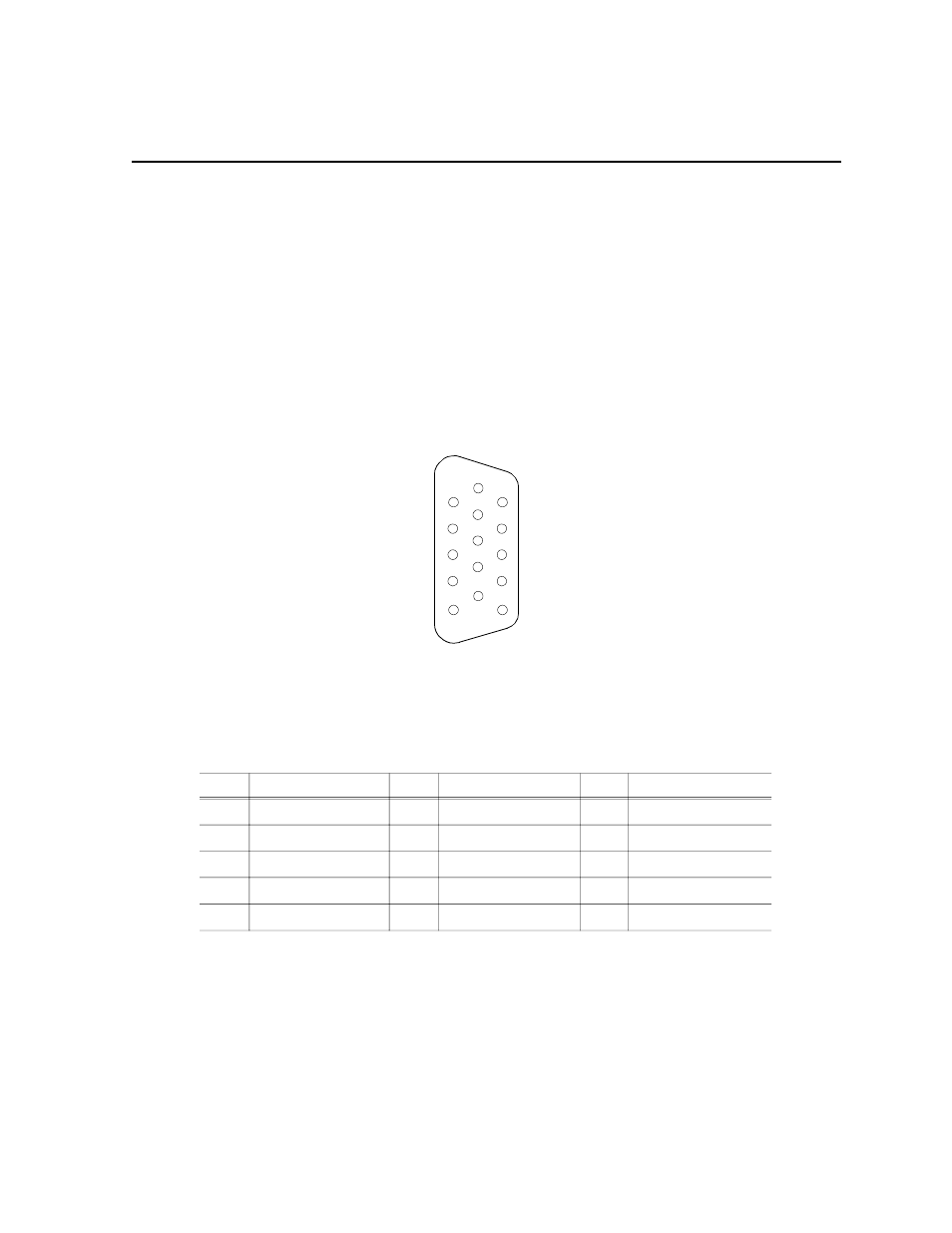
The S-VGA board has two rear panel connectors: one for the Monitor and one for a
Parallel Port The SVGA board communicates over the ISA bus. The S-VGA board
rear panel Monitor connector is a high density 15 female connector. Figure A-1 shows
the SVGA Monitor connector and Table A-1 lists the pin-outs.
Figure A-1. SVGA Board Monitor Connector
Table A-1. S-VGA Board Monitor Connector Pin-outs
Pin #
Signal
Pin #
Signal
Pin #
Signal
1
Analog Red Output
6
Ground
11
not used
2
Analog Green Output
7
Ground
12
not used
3
Analog Blue Output
8
Ground
13
Horizontal Sync
4
not used
9
Ground
14
Vertical Sync
5
not used
10
not used
15
not used
1
6
11
5
10
15