Grass Valley Trinix NXT v.3.3.1 User Manual
Page 152
152
Trinix NXT — Installation and Service Manual
Section 3 — Hardware Installation
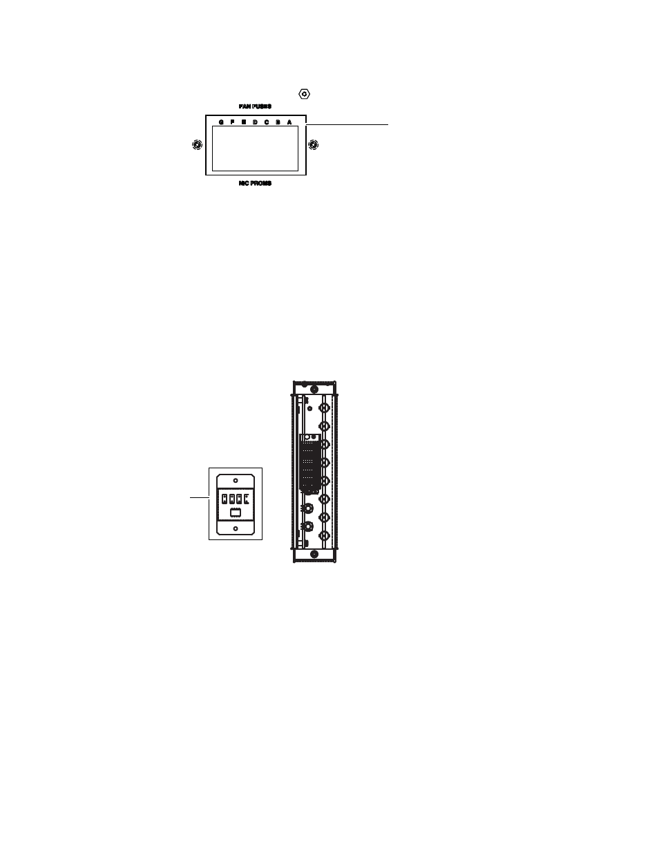
Figure 77. Fuse Location for the 256x512 Router
The 512x1024 Asymmetrical Frame
The fuse locations for the 512x1024 Asymmetric frame is similar to the
256x512 frame, except there are two fuse covers, one in the upper section
and one in the lower section. The upper fuses are for the fan modules, both
the upper (F110-F113) and lower fans (F210-F213). These fuses have LEDs
to indicate the presence of a blown fan fuse. The Fuse cove has little holes
that may be used to see if any of these LEDs are lighted, which indicates a
blown fan fuse. The fuses are labeled “Fan Fuse A” or “B” to indicate which
fuse goes with which fan module in the 1 RU fan assembly.
Figure 78. Fuse Location for the 512x1024 Router
Two fuses under each cover support additional power supply redundancy
for the TRX-OPM and Broadlinx (NR-33000) cards. The fuses are: F101,
F105, F201, and F205.
•
Fuses F101 and F105, fuse the secondary 48V DC path from the A1 & B1
power supply trays to the lower portion of the frame supporting the
lower TRX-OPM and the secondary NR-3300.
•
Fuses F201 & F205, fuse the secondary 48V DC path from the A2 & B2
power supply trays to the upper portion of the frame supporting the
upper TRX-OPM, and primary NR-3300.
CAUTION Unlike the Fan Fuses, fuses F101, F105, F201 & F205 do not have the Blown-
Fuse LED indicators!
071827611_fuse-loc_256x512
Location of Fuses
071827612_Fuse location 512x1024
Location of Fuses