Output monitor connection, Qc station switcher control panel, Jupiter control system – Grass Valley Trinix NXT v.3.3.1 User Manual
Page 202
Advertising
202
Trinix NXT — Installation and Service Manual
Section 3 — Hardware Installation
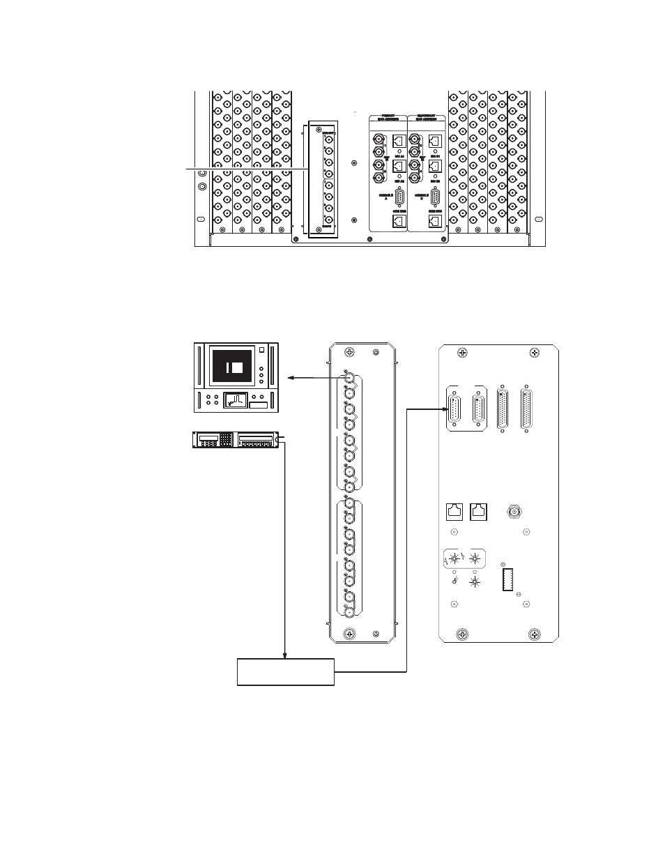
Figure 115. Example of the Output Monitor Connection for the 256 x 512 all-NTSC switcher.
Figure 116. Example of the Output Monitor Connection for the 512 x 512 all-NTSC switcher.
071827609_TRX-SR Output Monitoring Connection
Output Monitor
Connection
QC STATION
SWITCHER CONTROL
PANEL
1024
512
2048
1536
16
112
1
15
80
48
64
80
48
64
0
ULTRA
MONITOR
16
32
96
112
3
5
4
12
11
13
3
6
5
2
4
8
14
13
12
11
10
8
0
7
1
9
15
FRAME
6
10
7
9
LEVEL
32
SUPER
0
96
2
0
14
C
B
A
INT XPT CNTL
OUTPUT EXPAND
INPUT EXPAND
60Hz ENABLE
SYNC REDUNDANT
PS IFC
FAN IFC
XPT BUS
COM BUS
COM BUS
ALARM
B
A
B
A
B
A
B
1
4
3
2
MON
OP
A
1
2
4
3
IN
REF
JUPITER
CONTROL SYSTEM
Advertising
This manual is related to the following products: