Configuration dip switches – Grass Valley Trinix NXT v.3.3.1 User Manual
Page 231
Trinix NXT — Installation and Service Manual
231
Trinix Asymmetrical Frames
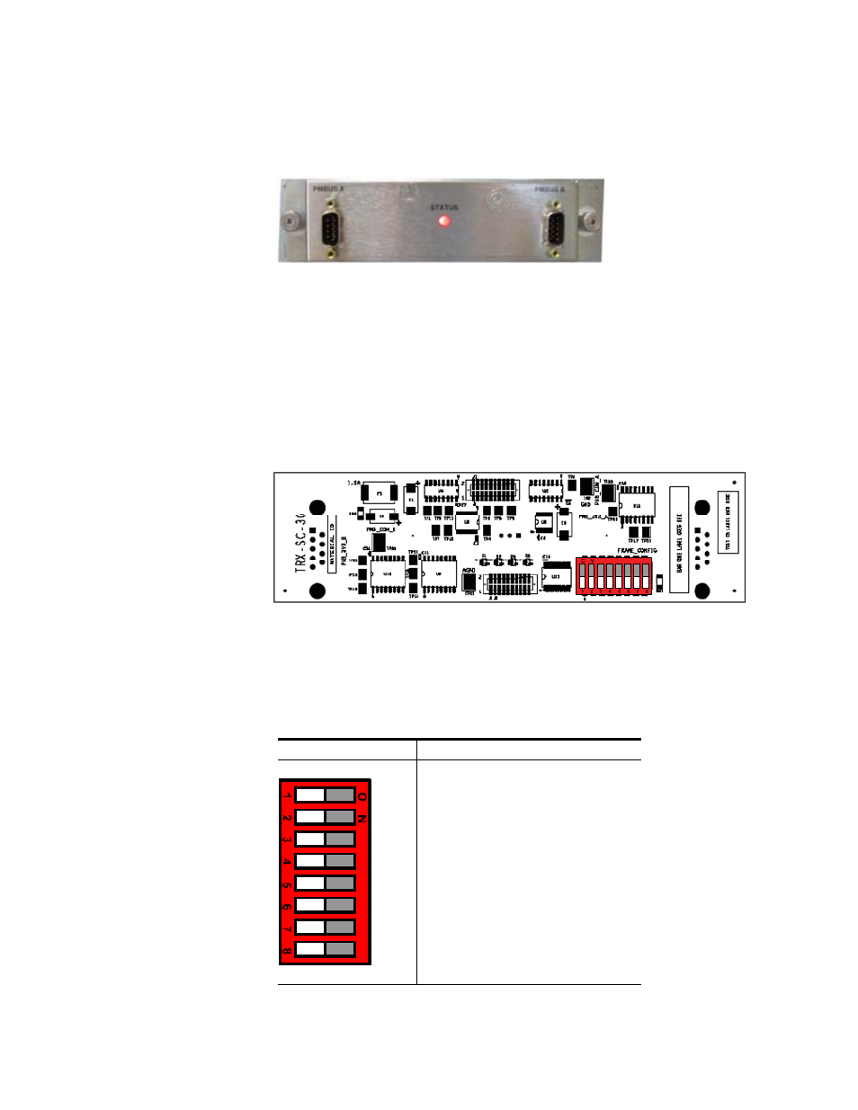
be configured, by means of Dual In-line Package (DIP) switches, to match
the power supply configuration of each system.
Figure 138. TRX-SC Board
Configuration DIP Switches
The configuration DIP switches are located on the left side of the back of the
TRX-SC board (
).
Note
The DIP switches will be highlighted in red in the following TRX-SC board
examples in this appendix.
Figure 139. TRX-SC Configuration DIP Switch Location
The DIP switches will control the number of power busses and the number
of external power supply frames to monitor. Refer to
for the con-
figuration DIP details.
Table 50. TRX-SC Configuration Switch Details
Switches
Details
SW 1 = BUS A ENABLE
SW 2 = BUS A EXPANSION ENABLE (Future use)
SW 3 = BUS B ENABLE
SW 4 = BUS B EXPANSION ENABLE (Future use)
SW 5 = N/A
SW 6 = N/A
SW 7 = N/A
SW 8 = N/A
071827609_TRX-SC-3G-b
oard_Configuration DIP Switch