SMA SMC 9000TL Installation User Manual
Page 16
16
SMC9-11TLRP-IA-en-51
Installation Manual
4 Product Description
SMA Solar Technology AG
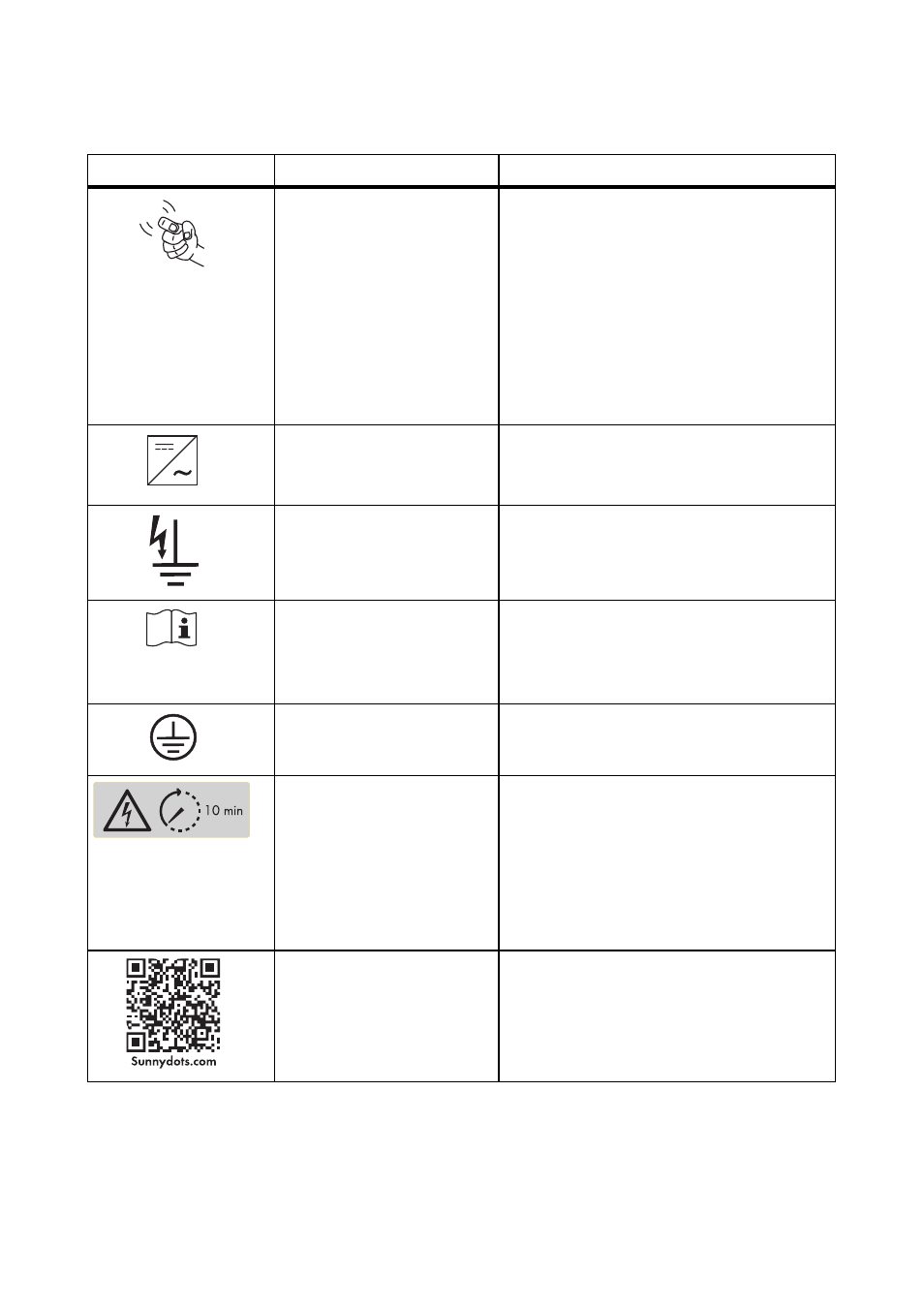
Symbols on the Inverter
Icon
Designation
Explanation
Tapping
You can operate the display by tapping it:
• Single tap: Switch on display
illumination or switch to the next
display message.
• Tapping twice: The inverter shows the
display messages from the start-up
phase.
After two minutes, the backlight switches off
automatically.
Inverter
This symbol defines the function of the green
LED. The green LED indicates the operating
state of the inverter.
Earth fault
This symbol defines the function of the red
LED. The red LED indicates an earth fault, a
defective varistor or a defective string fuse.
Observe the documentation. This symbol defines the function of the
yellow LED which indicates a fault or
disturbance. Read the manual to remedy the
fault or disturbance.
Protective conductor
This symbol indicates the position for the
protective conductor connection.
Danger to life due to high
voltages in the inverter;
observe waiting time.
High voltages that can cause fatal electric
shocks are present in the live components of
the inverter. The capacitors take ten minutes
to discharge. Prior to performing any work
on the inverter, disconnect it from all voltage
sources, as described in this document
(see section 9).
QR Code
®
The QR Code
®
links to the SMA Bonus
Programme (for information see