SMA SMC 9000TL Installation User Manual
Page 52
52
SMC9-11TLRP-IA-en-51
Installation Manual
8 Commissioning
SMA Solar Technology AG
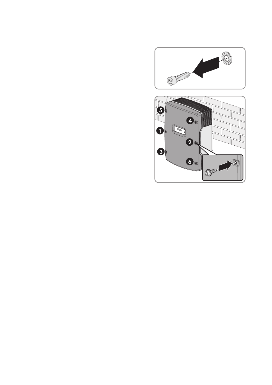
1. Close the inverter and earth the enclosure lid:
☑ The teeth of the conical spring washers are pushed into the enclosure lid. This ensures that
the enclosure lid is earthed.
2. Connect the DC connectors to the inverter.
3. Seal all unused DC inputs using the DC connectors with sealing plugs.
4. Check the ESS for wear (see section 10.6).
5. Switch on the miniature circuit-breaker.
☑ The start-up phase begins. All three LEDs are glowing or flashing.
☑ The green LED is glowing and the start-up phase begins. The display shows the device type,
firmware version, country data set and operating mode of the SMA Power Balancer
consecutively. After the start-up phase has been completed, the current power, reactive
power and displacement power factor cos φ are displayed.
✖ Have all LEDs gone out?
The ESS is not plugged in or there is no DC input voltage.
• Plug in the ESS securely or wait until DC input voltage is present.
✖ Is the green LED flashing?
The DC input voltage is still too low.
• Once the DC input voltage is sufficiently high, the inverter will start to operate.
✖ Is the yellow or red LED glowing or flashing?
There is probably a fault or warning present.
• Rectify the fault or warning (see section 10.1 "LED Signals", page 56).
• Attach one conical spring washer to each
screw. The grooved side of the conical spring
washer must point to the screw head.
• Secure the enclosure lid with screws in the
sequence 1 to 6 (torque: 6 Nm).