Display and leds, 3 display and leds – SMA SMC 9000TL Installation User Manual
Page 19
Installation Manual
SMC9-11TLRP-IA-en-51
19
SMA Solar Technology AG
4 Product Description
The display and the LEDs of the inverter are located on the enclosure lid and indicate the operating
state of the inverter.
The display shows the current operating data of the inverter (e.g. mode, performance, input voltage)
and errors or faults (see section 10.2 "Display Messages", page 58).
The LEDs indicate the operating state of the inverter, and clarify the messages in the display using
different blink codes (see section 10.1 "LED Signals", page 56).
Korean mark of conformity
The inverter complies with the
requirements of the applicable Korean
guidelines.
Chinese mark of conformity
The inverter complies with the
requirements of the applicable Chinese
guidelines.
4.3
Display and LEDs
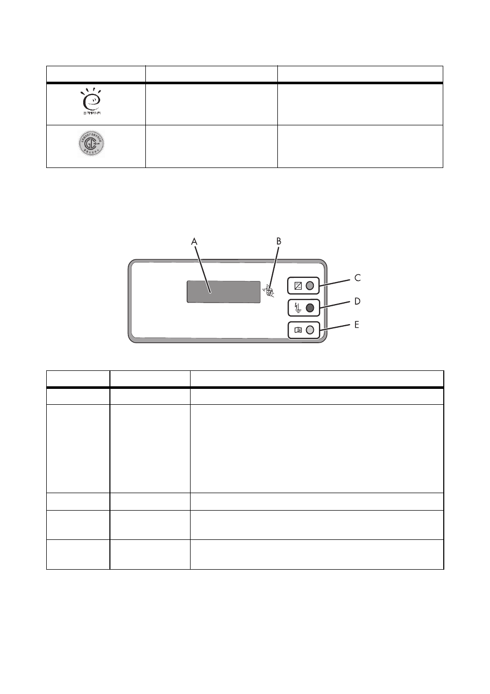
Figure 5:
Design of the display
Position
Designation
Explanation
A
Display
2-line LC text display for displaying operating data
B
Tap symbol
You can operate the display by tapping it:
• Tapping once: Switch on display illumination or switch to
the next display message.
• Tapping twice in quick succession: The inverter shows the
display messages from the start-up phase.
After two minutes, the backlight switches off automatically.
C
Green LED
Indicates the operating state of the inverter.
D
Red LED
Indicates an earth fault, a defective varistor or a defective string
fuse.
E
Yellow LED
Indicates an error or fault. Read the manual to rectify the error
or fault.
Icon
Designation
Explanation