SMA SMC 9000TL Installation User Manual
Page 39
Installation Manual
SMC9-11TLRP-IA-en-51
39
SMA Solar Technology AG
6 Electrical Connection
Cable requirements:
The cable must be of type PV1-F, UL-ZKLA or USE2 and comply with the following properties:
☐ External diameter: 5 mm … 8 mm.
☐ Conductor cross-section: 2.5 mm² … 6 mm²
☐ Number of conductors: at least seven
☐ Nominal voltage: at least 1,000 V
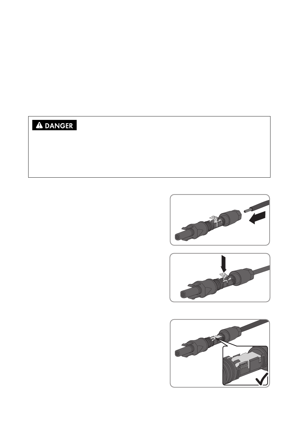
Proceed as follows to assemble each DC connector.
1. Strip 12 mm of the cable insulation.
☑ The clamping bracket clicks audibly into place.
Electric shock due to high voltages
When exposed to sunlight, the PV array generates dangerous DC voltage which is present in the
DC conductors and the live components of the inverter. Touching the DC conductors can result in
lethal electric shocks.
• Do not touch the DC conductors.
2. Route the stripped cable all the way into the DC
connector. Ensure that the stripped cable and the
DC connector have the same polarity.
3. Push the clamping bracket down.
☑ The stranded wire can be seen inside the
clamping bracket chamber.
+
+
+