Communication cable specifications, Wiring the network cable connectors, Network termination – Yaskawa 1000 Series Drive Option - CANopen Technical Manual User Manual
Page 12: Eds files, Figure 5, Apply a, Ned in, Figure 6, 5 installation procedure
5 Installation Procedure
12
YASKAWA ELECTRIC
SIEP C730600 45B 1000-Series Option SI-S3 Technical Manual
◆
Communication Cable Specifications
To ensure proper performance Yaskawa recommends using CANopen dedicated communication cables only.
◆
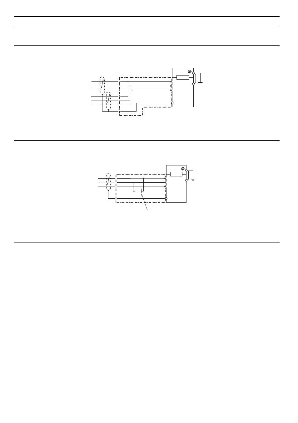
Wiring the Network Cable Connectors
The CANopen option must be connected to the network using a 9 pin D-sub connector wired like shown in
Figure 5
Figure 5 Wiring Diagram
◆
Network Termination
Both ends of a CANopen network have to be terminated with a 120
Ω resistor. As the CANopen Option has no build in termination resistor, make
sure to apply a termination resistor as shown in
if the CANopen Option is the last node in the network.
Figure 6
Figure 6 Termination Resistor Installation
◆
EDS Files
For easy network implementation of drives equipped with a CANopen Option, an EDS file can be obtained from:
Europe: http://www.yaskawa.eu.com
Japan: http://www.e-mechatronics.com
Other areas: contact a Yaskawa representative
<1> The FE terminal on the CANopen Option must be connected to the drive ground terminal using the delivered ground wire.
<1> The FE terminal on the CANopen Option must be connected to the drive ground terminal using the delivered ground wire.
D-sub Connector
CAN_SHLD
CAN_L
CAN_GND
CAN_H
CANopen Cable Connector
(Shell)
CANopen Cable
Drive
SI-S3
7
2
3
CN5
FE
<1>
Drive
D-sub Connector
SI-S3
CAN_SHLD
CAN_L
CAN_GND
CAN_H
7
2
3
CANopen Cable Connector
CN5
FE
(Shell)
<1>
CANopen Cable
120
Ω
For the last node on the network,
apply a terminating resister.