4 canopen option components, Canopen option, Communication connector – Yaskawa 1000 Series Drive Option - CANopen Technical Manual User Manual
Page 8: 4canopen option components
8
YASKAWA ELECTRIC
SIEP C730600 45B 1000-Series Option SI-S3 Technical Manual
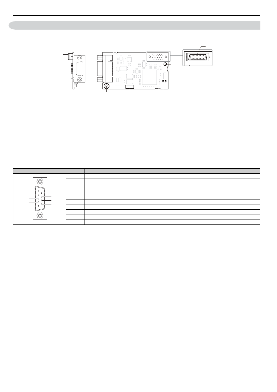
4 CANopen Option Components
4
CANopen Option Components
◆
CANopen Option
Figure 1
Figure 1 Option Card
◆
Communication Connector
The CANopen Option is connected to the network using a 9 pin D-sub connector. The pin assignment is explained in
.
Table 2 Communication connector (9 pin D-sub)
A – Communication cable connector
(9 pin D-sub)
<1>
Refer to CANopen Option Status LEDs on page 9
for details on the LEDs.
<2> The ground wire provided in the option shipping package must be connected during installation.
E – LED (ERR)
B – Connector (CN5)
F – Model number
C – Installation hole
G – Ground terminal
(installation hole)
D – LED (RUN)
CANopen Connector
Pin
Signal
Description
1
–
–
2
CAN_L
CAN_L bus line (dominant low)
3
CAN_GND
CAN Ground
4
–
–
5
CAN_SHLD
CAN shield
6
–
–
7
CAN_H
CAN_H bus line (dominant high)
8
–
–
9
–
–
–
CAN_SHLD
CAN shield
Underside
B
A
C
D
E
G
SI-S3
F
Looking from the connector
1
5
6
9
7
8
2
3
4