Yaskawa 1000 Series Drive Option - CANopen Technical Manual User Manual
Page 30
10 Process Data Objects (PDO)
30
YASKAWA ELECTRIC
SIEP C730600 45B 1000-Series Option SI-S3 Technical Manual
Subindex 2: MEMOBUS/Modbus Address of Content
This subindex contains the address of the drive MEMOBUS/Modbus register that the object is linked to. Setting FFFF (Hex) to subindex 2 will
disable the object (i.e., the value in subindex 1 will be 0).
Subindex 3: Filter Value
Sets the filter value for the Change of State event if the object is mapped to a TxPDO with transmission type FE (Hex).
When the filter value is set to 0000 (Hex), the Change of State event will be triggered whenever the value of the MEMOBUS/Modbus register
specified in subindex 2 changes. When the filter is set to FFFF (Hex), the Change of State event will not be triggered.
Subindex 4: Filter Type
This subindex is used to select the filter type. Two filter types are available, an analog filter and a bitmask filter.
If the analog filter is selected (subindex 4 = 0), the value of the MEMOBUS/Modbus register specified in subindex 2 must change by the amount set
in subindex 3 before a Change of State event is triggered. The filter has no unit. The resolution depends on the value of the MEMOBUS/Modbus
register content.
If the bitmask filter is selected (subindex 4 = 1), the Change of State event will be triggered whenever the value of the MEMOBUS/Modbus register
specified in subindex 2 changes in any bit except the masked bits. If a bitmask is set, the TxPDO will be triggered only if bits that are set to “0” in
the mask change. Bits set to “1” are ignored.
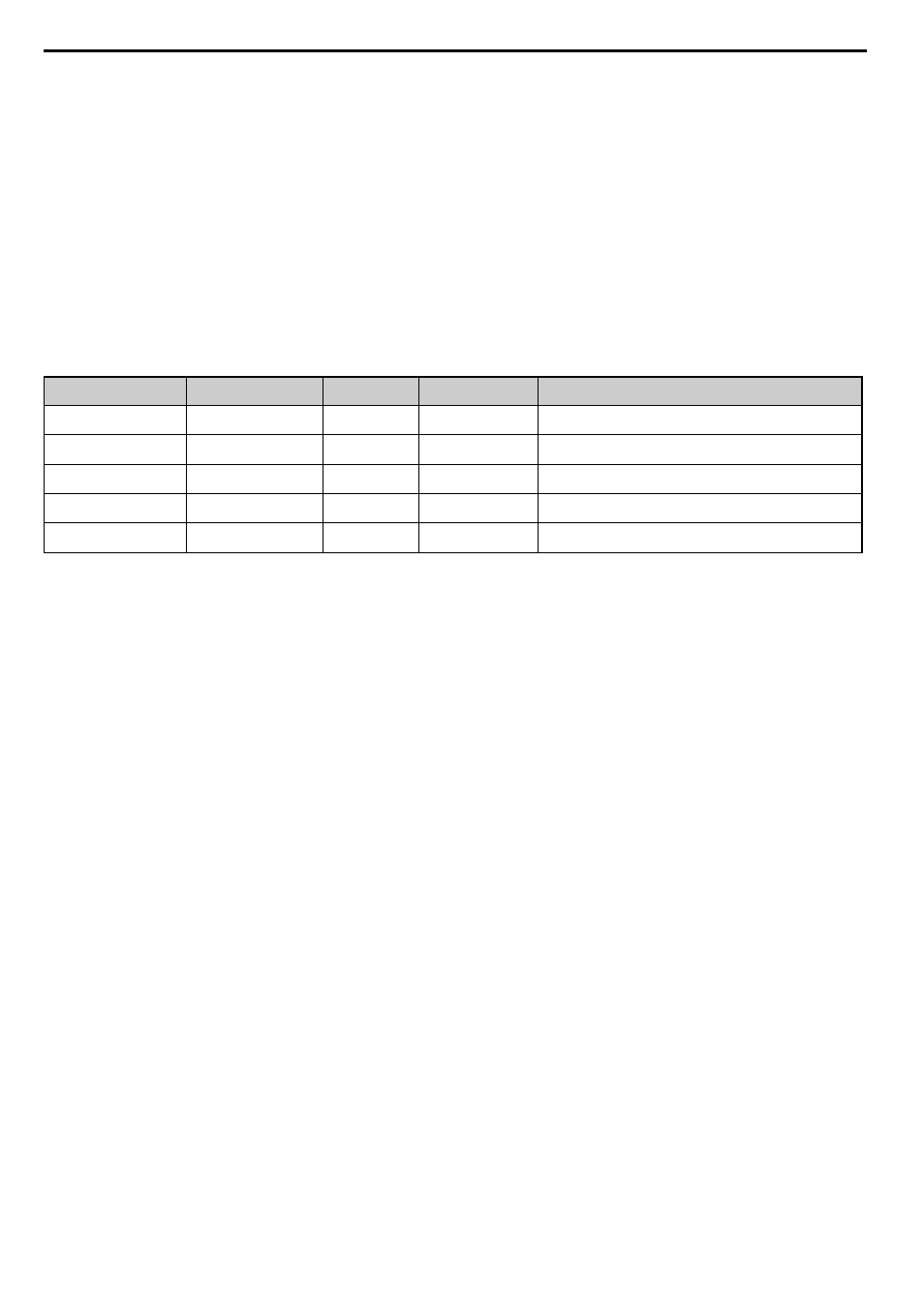
Examples
Object Content
(Subindex 2)
Filter Value (Subindex 3)
Filter Type
(Subindex 4)
Resolution of Object
Value
Object Value Behavior
Output frequency (0041 Hex)
A (Hex)
0 (Analog)
0.01 Hz
Change of State is triggered when the output frequency changes by more
than 0.10 Hz.
Output voltage (0054 Hex)
32 (Hex)
0 (Analog)
0.1 V
Change of State is triggered when the output voltage changes by more
than 5.0 V.
Drive Status (0020 Hex)
0
1 (Bitmask)
-
Change of State is triggered when any bit in the drive status word
changes.
Drive Status (0020 Hex)
03 (Hex)
0000 0000 0000 0011 (Bin)
1 (Bitmask)
-
Change of State is triggered by any status change except “During Run”
(bit 0) and “During Zero Speed” (bit 1).
Drive Status (0020 Hex)
09 (Hex)
0000 0000 0000 1001 (Bin)
1 (Bitmask)
-
Change of State is triggered by any status change except “During Run”
(bit 0) and “During Fault Reset Input” (bit 3).