Prior to installing the option card, Installing the option card, 5 installation procedure – Yaskawa 1000 Series Drive Option - MECHATROLINK-II Technical Manual User Manual
Page 12
5 Installation Procedure
12
YASKAWA ELECTRIC SIEP C730600 50A YASKAWA AC Drive-Option Card MECHATROLINK-II Technical Manual
Prior to Installing the Option Card
Prior to installing the MECHATROLINK-II Option, wire the drive and make necessary connections to the drive
terminals. For more information on wiring and connecting the drive, refer to the technical manual for the drive the
MECHATROLINK-II option card is connected to. Verify that the drive runs normally without the option installed.
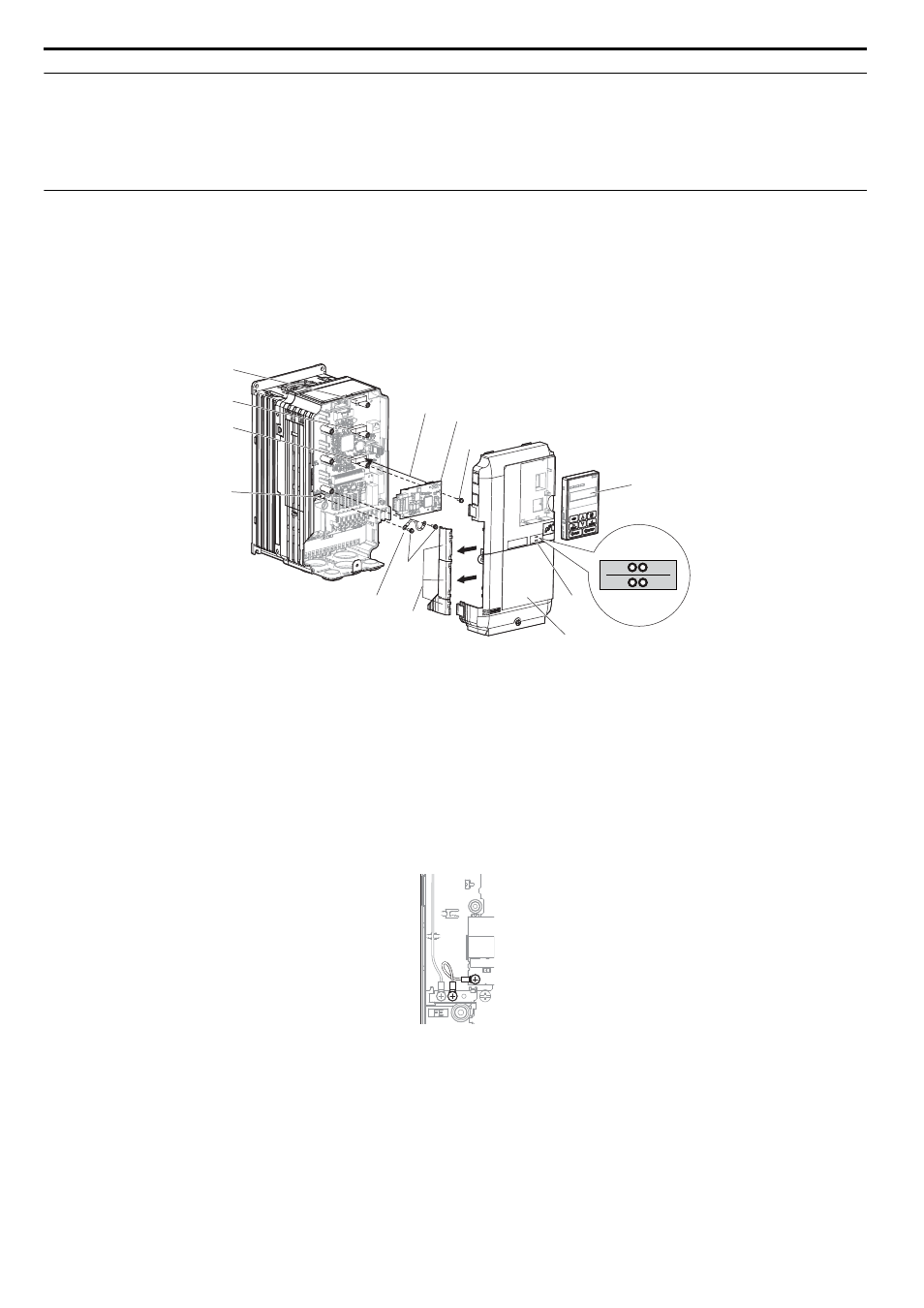
Installing the Option Card
Insert the option card in the CN5-A connector located on the drive’s control board.
See the drive manual for directions on removing the front cover.
1.
Shut off power to the drive, wait the appropriate amount of time for voltage to dissipate, then remove the
operator and front cover. Refer to the drive technical manual for direction on removing the front cover.
2.
Insert the CN101 connector on the option card into the CN5-A connector on the drive, then fasten it into place
using one of the screws included with the option card.
Figure 2
Figure 3 Installing the Option Card
3.
Connect the ground lead line to the ground terminal using one of the screws delivered with the option card.
Note: There are only two screw holes on the drive for ground terminals. If three option cards are connected, two of the lead lines will
need to share the same ground terminal.
Figure 3
Figure 4 Connecting the Ground Terminal
A – Connector CN5-C
G – Lead line
B – Connector CN5-B
H – Mounting screw (M3)
C – Connector CN5-A
I – Use wire cutters to create an opening
for cable lines
D – Drive grounding terminal (FE)
J – Operator
E – Insert connector CN101 here
K – LED label
F – Option card
L – Front cover
H
G
A
E
H
F
J
K
B
C
D
I
L
TX
RX
ERR
RUN
SI-T3