Mechatrolink-ii communications cables – Yaskawa 1000 Series Drive Option - MECHATROLINK-II Technical Manual User Manual
Page 13
5 Installation Procedure
YASKAWA ELECTRIC
SIEP C730600 50A YASKAWA AC Drive-Option Card MECHATROLINK-II Technical Manual
13
4.
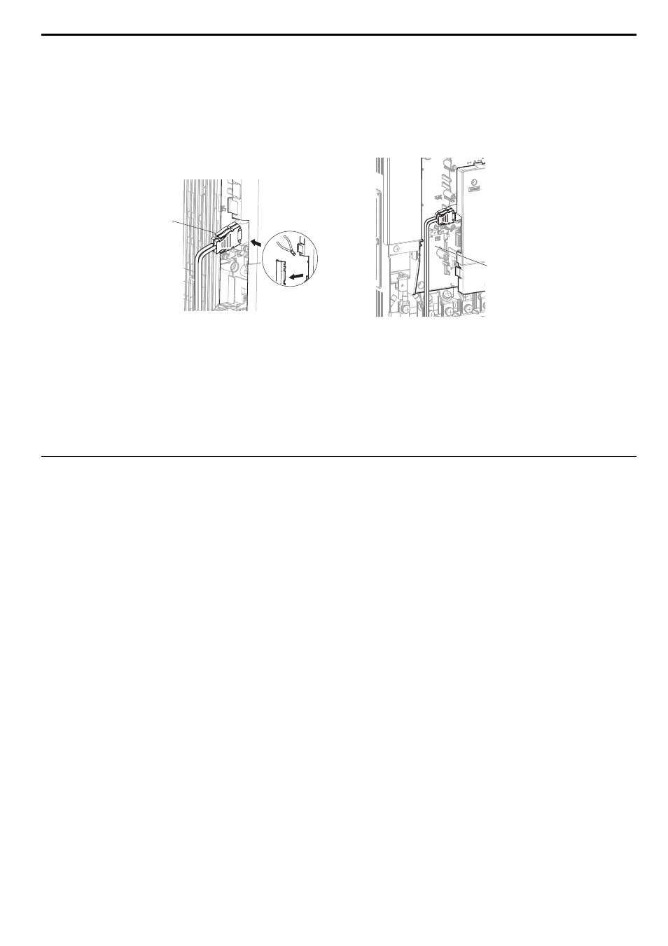
Wire the MECHATROLINK-II to the connector on the option card.
When installing option cards to drive models CIMR-A2A0004 through 0040 and to models CIMR-A4A0002
through 0023, the cables connected to the option might need to be routed through the top cover to the outside.
In this case, cut out the perforated openings on the left side of the drive top cover. Make sure no sharp edges are
left that may damage the cable.
Models CIMR-A2A0056 through 0211 and 4A0031 through 0165 have enough space to keep all wiring inside
the unit.
Figure 4
Figure 5 Wiring space
5.
Place the front cover back onto the drive as it was before.
Note: 1. Take care when wiring the option card so that the front cover easily fits back onto the drive.
2. Install Cable Cover option to maintain the drive Enclosure Type.
6.
Attach the LED label packaged with the option card as shown in
MECHATROLINK-II Communications Cables
Wire the MECHATROLINK-II communications cables to the communications connector (CN3). Install
MECHATROLINK-II communications cables apart from main-circuit wiring and other electrical and power lines.
Note: 1. For communications cables, use special shielded twisted-pair cables for MECHATROLINK communications.
Recommended cable: JEPMC-W6002--E
JEPMC-W6003--E (with a core)
2. Connect the terminator (model No.: JEPMC-W6022-E) on the end of the communication lines.
3. Maximum transmission distance is 50 m. Minimum wiring distance between stations is 0.5 m.
A – Opening for cable lines
(CIMR-A2A0004 to 0040,
4A0002 to 0023)
B – Space for wiring
(CIMR-A2A0056 to 0211,
4A0031 to 0165)
<1> is the length (m).
B
A