5 installation procedure – Yaskawa 1000 Series Drive Option - Profibus-DP Technical Manual User Manual
Page 15
5 Installation Procedure
YASKAWA ELECTRIC
SIEP C730600 42B 1000-Series Option SI-P3 Technical Manual
15
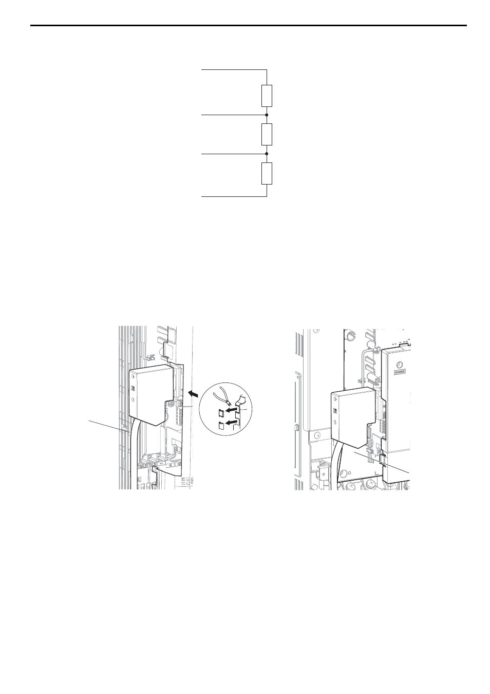
Termination resistors without inductors as shown in
can only be used for baud rates below 1.5 Mbps.
Baud rates 1.5 Mbps and higher require termination with resistors and inductors as shown in
.
Figure 9
Figure 9 Cable Termination of the Option Cable to EN50170
(Pin Numbers for a 9-pin D-sub Connector)
7.
Route the option wiring.
Depending on the drive model, some drives may require routing the wiring through the side of the front cover to
the outside. In these cases, use diagonal cutters to cut out the perforated openings in the left side of the drive
front cover as shown in
-A and leave no sharp edges to damage wiring.
Route the wiring inside the enclosure as shown in
-B for drives that do not require routing through the
front cover. Refer to the Peripheral Devices & Options section of the drive Technical Manual for more
information.
Figure 10
Figure 10 Wire Routing Examples
8.
After connecting the prepared cable for the 9-pin D-sub communication connector CN5, recheck the option wire
routing performed in step 6.
A – Route wires through the openings
provided on the left side of the front
cover.
<1> The drive will not meet NEMA Type 1 requirements if wiring is exposed outside the enclosure.
B – Use the open space provided inside
the drive to route option wiring.
390
Ω
B - Data line
DGND (pin 5)
RxD/TxD-N (pin 8)
RxD/TxD-P (pin 3)
VP (pin 6)
A - Data line
220
Ω
390
Ω
A
B