7 option data and i/o maps, Conventional formats, Memory maps – Yaskawa 1000 Series Drive Option - Profibus-DP Technical Manual User Manual
Page 20: 7option data and i/o maps, High-speed i/o data, Basic and extended register maps
20
YASKAWA ELECTRIC SIEP C730600 42B 1000-Series Option SI-P3 Technical Manual
7 Option Data and I/O Maps
7
Option Data and I/O Maps
Conventional Formats
The configuration tool of PROFIBUS-DP master sets the input and output data length of SI-P3 from Extended Data 1
(32 bytes), Extended Data 2 (12 bytes), and Basic Data (6 bytes).
Conventional formats have two message types: High-speed I/O Data and MEMOBUS/Modbus message. Set parameter
F6-32 to 1 to use conventional formats.
High-Speed I/O Data
High-speed I/O data is directly transferred between the drive and controller or PLC. When the drive is set for
PROFIBUS-DP communications, the drive Run/Stop and Frequency Reference commands are transferred within 2 ms
after being received by the option.
MEMOBUS/Modbus Message
MEMOBUS/Modbus message data is transferred between the drive and controller or PLC using MEMOBUS/Modbus
messages. All drive parameters and data can be accessed through MEMOBUS/Modbus. The data in this message type is
transferred to the drive after being received and edited by the option and more time is required to return the data to the
master. The master must synchronize the timing of sending and receiving the data by a process called handshaking.
Refer to Handshaking Register on page 25
Memory Maps
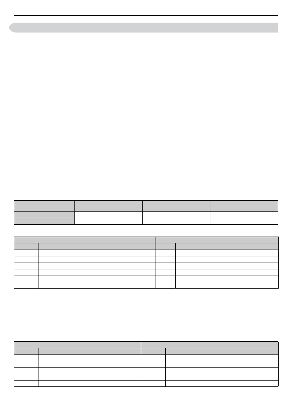
The following memory maps show the I/O data bytes.
Basic and Extended Register Maps
Table 9 Basic Data Register Map Detail
Table 10 Extended Data 1 Register Map
Basic Data
(6 bytes)
Extended Data 1
(32 bytes)
Extended Data 2
(12 bytes)
High-speed I/O Data
Bytes 0 to 5
Bytes 0 to 15
Bytes 0 to 3
MEMOBUS/Modbus Data
–
Bytes 16 to 31
Bytes 4 to 11
Output (Master Device to Drive)
Input (Drive to Master Device)
Byte
<1> Enabled in CLV, AOLV/PM, and CLV/PM control modes (A1-02 = 3, 6, or 7).
<2> Set when network communication is designated as the source of the torque limit and torque reference (F6-06 = 1). When enabled, d5-01
determines whether the value is read as the torque limit value (d5-01 = 0) or as the torque reference value (d5-01 = 1). In CLV/PM, this value is
read as the torque limit.
<3> Unit depends on the setting of o1-03 (Digital Operator Display Scaling). When the drive is operating in V/f Control or OLV/PM, the drive
output frequency becomes the input data.
<4> Data is displayed in units of 0.01 A for drives 7.5 kW and smaller, and in units of 0.1 A for drives 11 kW and larger. This convention is the same
regardless of drive duty mode selection.
Description
Byte
Description
0
Operation Command High Byte
0
Drive Status High Byte
1
Operation Command Low Byte
1
Drive Status Low Byte
2
Frequency Reference High Byte
2
Motor Speed High Byte
3
Frequency Reference Low Byte
3
Motor Speed Low Byte
4
Torque Reference/Torque Limit High Byte
4
Output Current High Byte
5
Torque Reference/Torque Limit Low Byte
5
Output Current High Byte
Output (Master Device to Drive)
Input (Drive to Master Device)
Byte
Description
Byte
Description
0
Operation Command High Byte
0
Drive Status High Byte
1
Operation Command Low Byte
1
Drive Status Low Byte
2
Frequency Reference High Byte
2
Motor Speed High Byte
3
Frequency Reference Low Byte
3
Motor Speed Low Byte
4
Torque Reference High Byte
4
Torque Reference Monitor High Byte