Memobus/modbus message area – Yaskawa 1000 Series Drive Option - Profibus-DP Technical Manual User Manual
Page 23
7 Option Data and I/O Maps
YASKAWA ELECTRIC
SIEP C730600 42B 1000-Series Option SI-P3 Technical Manual
23
MEMOBUS/Modbus Message Area
In the MEMOBUS/Modbus message area, MEMOBUS/Modbus messages are transferred to the option, and the
parameters in the drive can be set, read, and monitored. Up to four data items can be written or read at one time.
The option edits the MEMOBUS/Modbus message internally and transfers the message to the drive after receiving the
message; more time is required to return the message. Use the handshaking register to synchronize sending or receiving
of the data between the PROFIBUS-DP master and the option.
Refer to Handshaking Register on page 25
for details.
Execute an Enter command to validate the written data and write a parameter to the drive. Refer to the
MEMOBUS/Modbus Communications chapter of the drive Technical Manual for details on the Enter command and for a
list of monitor data using the MEMOBUS/Modbus message area.
Configuration of MEMOBUS/Modbus Command Message
shows the configuration of MEMOBUS/Modbus command messages when the Extended Data 1 is selected.
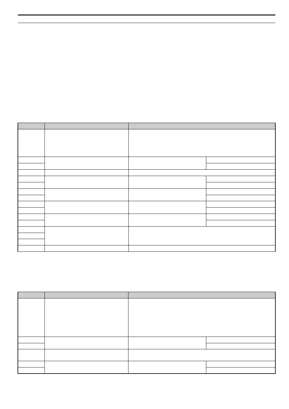
Table 14 MEMOBUS/Modbus Command Message
Configuration of MEMOBUS/Modbus Response Messages
shows the configuration of MEMOBUS/Modbus response messages when the Extended Data 1 is selected.
Table 15 MEMOBUS/Modbus Response Messages
Byte
<1> Setting is needed only for the write command. Select 00H for the read command.
Name
Function
16
Function code
MEMOBUS/Modbus command code:
03H: Read command (reading Drive internal data)
08H: Loop back
10H: Write command (writing data into the drive)
Other codes: Not supported.
17
Starting Resistor No.
Starting resistor No.
High Byte
18
Low Byte
19
Number of Data Items
Sets the number of bytes to read or write (only 2, 4, 6, or 8 allowed)
20
Data 1
Data word 1
High Byte
21
Low Byte
22
Data 2
Data word 2
High Byte
23
Low Byte
24
Data 3
Data word 3
High Byte
25
Low Byte
26
Data 4
Data word 4
High Byte
27
Low Byte
28
Reserved
Reserved
29
30
31
Handshaking Register
Refer to Handshaking Register on page 25
for details.
Byte
Name
Function
16
Function code
MEMOBUS/Modbus response codes
00H: Waiting for response from drive
03H: Response to read operation
10H: Response to write operation
83H: Read command error
90H: Write command error
Other codes: Not supported.
17
Starting resistor No.
Starting resistor No.
High Byte
18
Low Byte
19
Number of data items
Write: Set double number of written data items
Read: Set double number of read data items
20
Data word 1
High Byte
21
Low Byte